Introduction
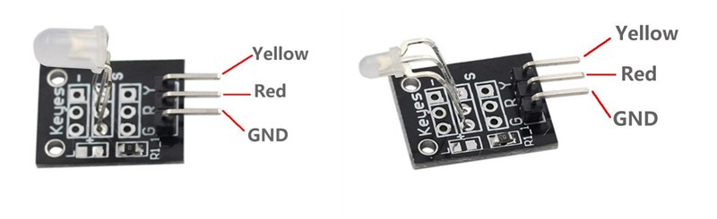
There are two kinds of dual-color Common-Cathode LED (as shown below) in this kit. Their only difference is the LED package size.
Components
– 1 * Raspberry Pi
– 1 * Network cable (or USB wireless network adapter)
– 1 * Dual-color Common-Cathode LED module
– Several jumper wires
Experimental Principle
Connect pin Yellow and Red to GPIOs of Raspberry Pi, then program the Raspberry Pi to change the color of the LED from red to yellow, and then use PWM to mix other colors.
Experimental Procedures
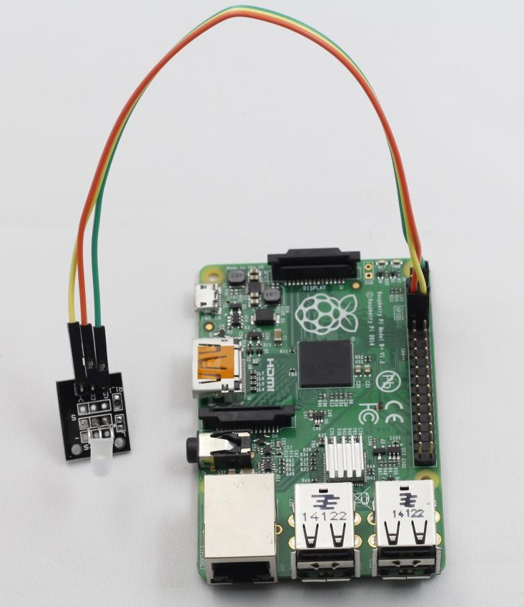
Step 1: Build the circuit
Raspberry Pi Dual-color LED
GPIO0 ————————————- R
GPIO1 ————————————- Y
GND ————————————– G
Step 2: Edit and save the code (see path/Rpi_SensorKit_code/05_doubleColorLed/doubleColorLed.c)
Step 3: Compile
gcc doubleColorLed.c –lwiringPi -lpthread
Step 4: Run
./a.out
You can see the dual-color LED flash yellow, red and then various mixed colors.
doubleColorLed.c
#include <wiringPi.h>
#include <softPwm.h>
#include <stdio.h>

#define uchar unsigned char

#define LedPinRed    0
#define LedPinGreen  1

void ledInit(void)
{
	softPwmCreate(LedPinRed,  0, 100);
	softPwmCreate(LedPinGreen,0, 100);
}

void ledColorSet(uchar r_val, uchar g_val)
{
	softPwmWrite(LedPinRed,   r_val);
	softPwmWrite(LedPinGreen, g_val);
}

int main(void)
{
	int i;

	if(wiringPiSetup() == -1){ //when initialize wiring failed,print messageto screen
		printf("setup wiringPi failed !");
		return 1;
	}
	//printf("linker LedPin : GPIO %d(wiringPi pin)\n",LedPin); //when initialize wiring successfully,print message to screen

	ledInit();

	while(1){
		ledColorSet(0xff,0x00);   //red
		delay(500);
		ledColorSet(0x00,0xff);   //green
		delay(500);
		ledColorSet(0xff,0x45);
		delay(500);
		ledColorSet(0xff,0xff);
		delay(500);
		ledColorSet(0x7c,0xfc);
		delay(500);
	}

	return 0;
}
Python Code
#!/usr/bin/env python
import RPi.GPIO as GPIO
import time

colors = [0xFF00, 0x00FF, 0x0FF0, 0xF00F]
pins = {'pin_R':11, 'pin_G':12}  # pins is a dict

GPIO.setmode(GPIO.BOARD)       # Numbers GPIOs by physical location
for i in pins:
	GPIO.setup(pins[i], GPIO.OUT)   # Set pins' mode is output
	GPIO.output(pins[i], GPIO.HIGH) # Set pins to high(+3.3V) to off led

p_R = GPIO.PWM(pins['pin_R'], 2000)  # set Frequece to 2KHz
p_G = GPIO.PWM(pins['pin_G'], 2000)

p_R.start(0)      # Initial duty Cycle = 0(leds off)
p_G.start(0)

def map(x, in_min, in_max, out_min, out_max):
	return (x - in_min) * (out_max - out_min) / (in_max - in_min) + out_min

def setColor(col):   # For example : col = 0x112233
	R_val = (col & 0x1100) >> 8
	G_val = (col & 0x0011) >> 0

	R_val = map(R_val, 0, 255, 0, 100)
	G_val = map(G_val, 0, 255, 0, 100)

	p_R.ChangeDutyCycle(R_val)     # Change duty cycle
	p_G.ChangeDutyCycle(G_val)

try:
	while True:
		for col in colors:
			setColor(col)
			time.sleep(0.5)
except KeyboardInterrupt:
	p_R.stop()
	p_G.stop()
	for i in pins:
		GPIO.output(pins[i], GPIO.HIGH)    # Turn off all leds
	GPIO.cleanup()