Introduction
How can an Evil Genius be sure that their prisoners are telling the truth? By a lie detector, of course. This lie detector uses an effect known as galvanic skin response. As a person becomes nervous – for example, when telling a lie – their skin resistance decreases. We can measure this resistance using an analog input and use an LED and buzzer to indicate an untruth. Use a multicolor LED that can display red to indicate a lie, green to indicate the truth, and blue to show that the lie detector should be adjusted by the variable resistor.
Components
– 1 * SunFounder Uno board
– 1 * USB data cable
– 1 * RGB module
– 1 * Buzzer module
– 1 * Potentiometer (250k)
– 1 * Resistor (470k)
– Several jumper wires
Experimental Principle
The subject’s skin resistance is measured by using the test subject as a resistor in a potential divider and a fixed resistor as the other. The lower their resistance is, the more analog input 0 will be pulled towards 5V. The higher the resistance gets, the closer to GND it will become.
The buzzer, despite of the noise level these things generate, is actually quite low in current consumption and can be driven directly from the SunFounder Uno digital pin. This experiment uses an RGB LED. In this case, however, we are not going to make it flash mixed colors but just turn one of the LEDs on at a time to display red, green, or blue.
Experimental Procedures
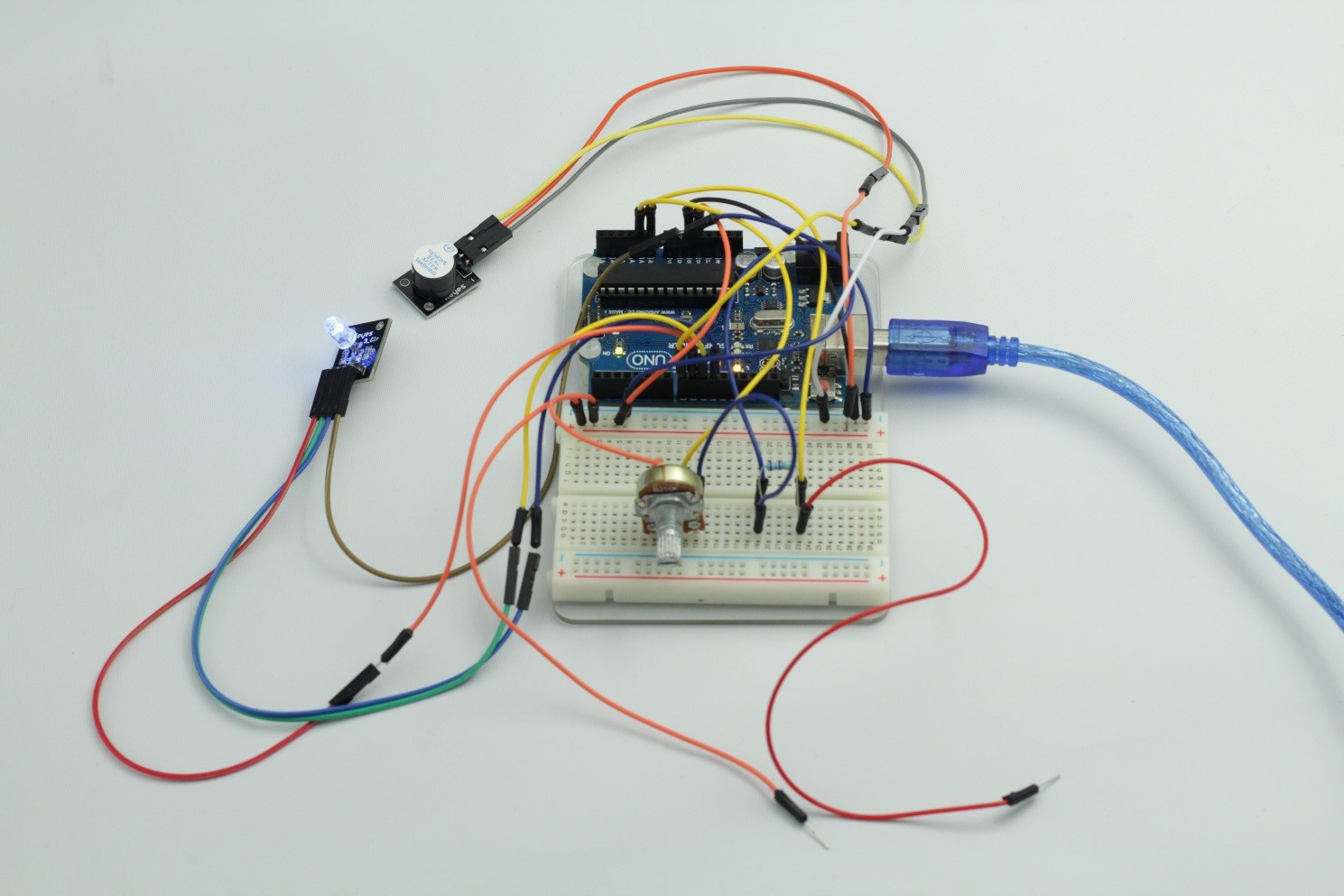
Step 1: Build the circuit
RGB Connection: Connect pin R to digital pin 9, G to digital pin 10, B to digital pin 11, and pin – to GND
Buzzer Connection: Connect pin S to digital pin 8, + to 5V, and pin – to GND
Potentiometer Connection: Connect the middle pin to analog port A1, and the other two pins to GND and 5V
Resistor Connection: connect one terminal to analog port A0, and the other to GND
Then, take out two jumper wires, and connect one end of one jumper wire to A0 and one end of the other wire to 5V.
Step 2: Program (Please refer to the example code in LEARN -> Get Tutorial on our website)
Step 3: Compile
Step 4: Upload the sketch to SunFounder Uno
To test the lie detector, you might need a test subject, as you will need one hand free to adjust the knob of the potentiometer.
Now ask your test subject to side down. First, let him/her touch the other end of the two jumper wires with two adjoining fingers. Then spin the knob of the pot until the LED turns green.
You may now “interrogate” the subject. If he/she lies to your questions, the LED will flash red and the buzzer beeps. If the LED flashes either red or blue, you should adjust the knob until it changes to green again. Then continue the interrogation.
Code
| #include “color.h” #include “rgb.h” #include “buzzer.h”int band = 70;void setup() { pinMode(8, OUTPUT);//the buzzer pin attach to pinMode(9, OUTPUT);//the r pin of the RGB attach to pinMode(10, OUTPUT);//the g pin of the RGB attach to pinMode(11, OUTPUT);//the b pin of the RGB attach to }void loop() { int potVal = analogRead(A1); int senVal = analogRead(A0); if(senVal < potVal – band) { setColor(9, 10, 11, Blue); } else if(senVal > potVal + band) { setColor(9, 10, 11, Red); beep(8); } else { setColor(9, 10, 11, Green); } } |