Introduction
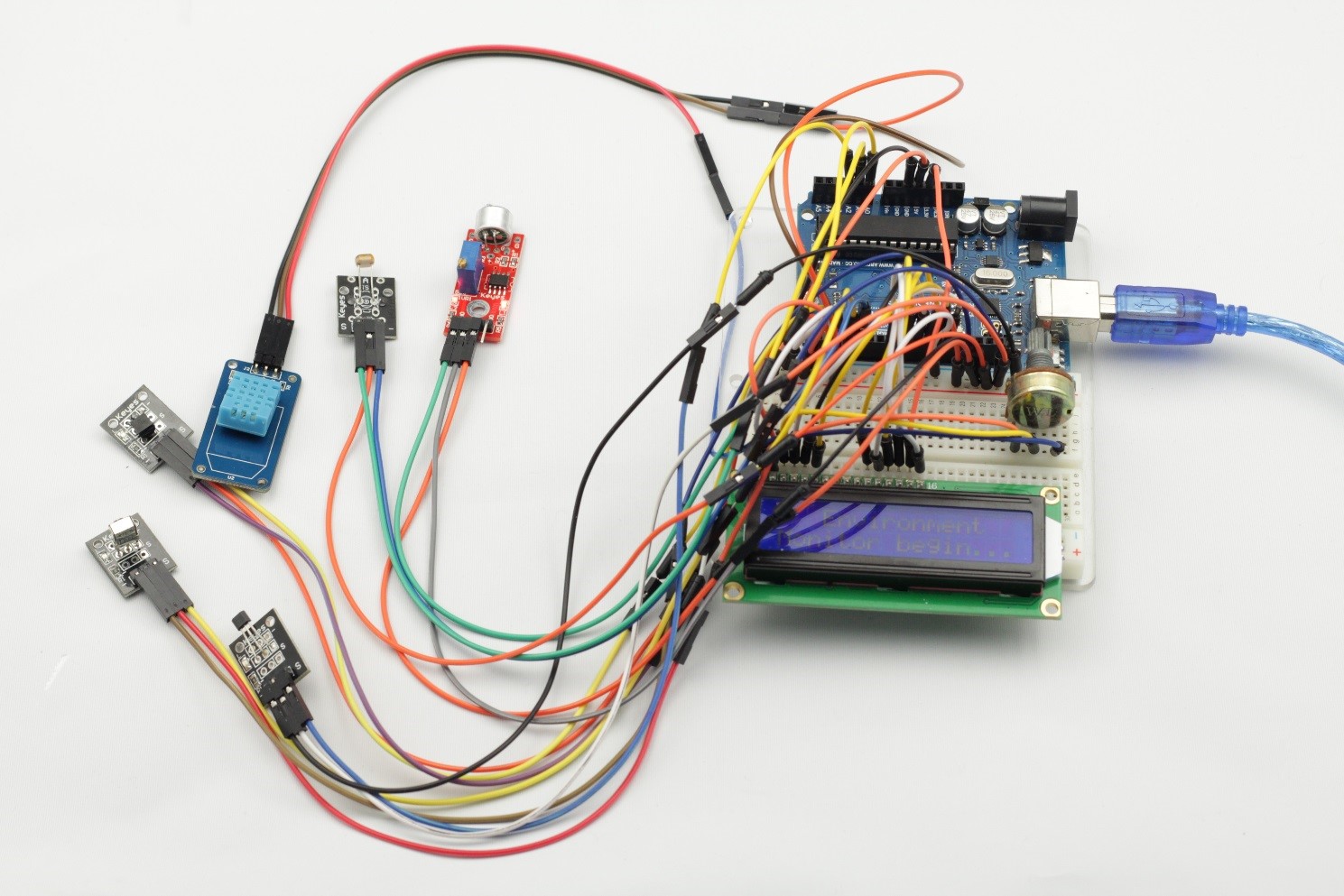
In this lesson, we will use a humiture sensor module, a DS18B20 module, an infrared receiver module, a high-sensitive voice sensor module, a photoresistor module, an analog-hall sensor module, an LCD1602 and a remote control to build an intelligent environment monitoring system.
Components
– 1 * SunFounder Uno board
– 1 * USB data cable
– 1 * DHT11 Humiture Sensor module
– 1 * DS18B20 module
– 1 * Infrared Receiver module
– 1 * Remote Control
– 1 * High-sensitive Voice Sensor module
– 1 * Photoresistor module
– 1 * Analog Hall Sensor module
– 1 * LCD1602
– Several jumper wires
Experimental Principle
After power on, when you press the Power key, “Environment Monitor Begin:” will be displayed on the LCD. Press digital 1 key and it will display “DS18B20” and the current temperature; press digital 2 key and it will display “DHT11” and the current humidity; press digital 3 key and it will display “Big Sound” and the current sound level; press digital 4 key and it will display “Light Sensor” and the current light intensity; press digital 5 key and it will display “Analog Hall” and the current magnetic field intensity; if you press digital 6 key, the display will exit and stop.
Experimental Procedures
Step 1: Build the circuit
LCD1602 Connection: connect pin RS to D12; R/W to GND; E to D11; D4~D7 to D10, D9, D8, and D7; VSS to GND; VDD to 5V; A to 3.3V; K to GND
Infrared Receiver module connection: connect pin S to D3, pin – to GND, and + to 5V
DS18B20 module connection: connect pin S to D2, pin – to GND, and + to 5V
DHT11 Humiture Sensor module connection: connect pin S to D4, pin – to GND, and + to 5V
High-sensitive Voice Sensor module connection: connect pin A0 to analog port A0, pin – to GND, and + to 5V
Photoresistor module connection: connect pin S to analog port A1, pin – to GND, and + to 5V
Analog-hall sensor module connection: connect pin S to analog port A2, pin – to GND, and + to 5V
Step 2: Program (Please refer to the example code in LEARN -> Get Tutorial on our website)
Step 3: Compile
Step 4: Upload the sketch to SunFounder Uno
Now, press “Power” Key and you can see “Environment Monitor Begin:” on the LCD.
Press digital 1 key and it will show “DS18B20” and a temperature value.
Press digital 2 key – “DHT11” and current humidity.
Press digital 3 key – “Big Sound” and current sound level.
Press digital 4 key – “Light Sensor” and current light intensity.
Press digital 5 key – “Analog Hall” and the current magnetic field intensity.
Press digital 6 key and the display will exit and restore to null.
Code
| #include <IRremote.h> #include <LiquidCrystal.h> #include <OneWire.h> #include <DallasTemperature.h> #include <dht.h>LiquidCrystal lcd(12, 11,10, 9, 8, 7); dht DHT;const int irReceiverPin = 3; const int ledPin = 13; #define ONE_WIRE_BUS 2 OneWire oneWire(ONE_WIRE_BUS); DallasTemperature sensors(&oneWire); #define DHT11_PIN 4 #define soundPin A0 #define lightPin A1 #define hallPin A2IRrecv irrecv(irReceiverPin); decode_results results; float temValue = 0; #define irDelay 300 int lightVal = 0; int hallVal = 0;void setup() { pinMode(ledPin,OUTPUT); Serial.begin(9600); irrecv.enableIRIn(); lcd.begin(16, 2); sensors.begin(); //DS18B20 }void loop() { if (irrecv.decode(&results)) { irrecv.resume(); } delay(irDelay); if(results.value == 0xFFA25D) { Serial.println(results.value); while(1) { lcd.setCursor(0, 0); lcd.print(” Environment “); lcd.setCursor(0,1); lcd.print(“Monitor begin…”); if (irrecv.decode(&results)) { irrecv.resume(); } delay(irDelay); if(results.value != 0xFFA25D && results.value != 0xFFFFFFFF) { Serial.println(results.value); break; } } while(1) { if(results.value == 0xFF30CF) { lcd.clear(); while(1) { lcd.setCursor(0, 0); lcd.print(” DS18B20 “); temValue = readTem(); lcd.setCursor(0, 1); lcd.print(“Tem: “); lcd.print(temValue); lcd.print(” C”); if (irrecv.decode(&results)) { irrecv.resume(); } delay(irDelay); if(results.value != 0xFF30CF && results.value != 0xFFFFFFFF) { break; } } } else if(results.value == 0xFF18E7) { lcd.clear(); while(1) { int chk = DHT.read11(DHT11_PIN); lcd.setCursor(0, 0); lcd.print(” DHT11 “); lcd.setCursor(0, 1); lcd.print(“Hum: “); lcd.print(DHT.humidity,1); lcd.print(” %”); if (irrecv.decode(&results)) { irrecv.resume(); } delay(irDelay); if(results.value != 0xFF18E7 && results.value != 0xFFFFFFFF) { break; } } } else if(results.value == 0xFF7A85) { lcd.clear(); while(1) { lcd.setCursor(0, 0); lcd.print(” Big Sound “); lcd.setCursor(0, 1); lcd.print(“Sound: “); lcd.print(readSound()); if (irrecv.decode(&results)) { irrecv.resume(); } delay(irDelay); if(results.value != 0xFF7A85 && results.value != 0xFFFFFFFF) { break; } } } else if(results.value == 0xFF10EF) { lcd.clear(); while(1) { lightVal = readLight(); lcd.setCursor(0, 0); lcd.print(” Light Sensor “); lcd.setCursor(0, 1); lcd.print(“Light: “); lcd.print(lightVal); if (irrecv.decode(&results)) { irrecv.resume(); } delay(irDelay); if(results.value != 0xFF10EF && results.value != 0xFFFFFFFF) { break; } } } else if(results.value == 0xFF38C7) { lcd.clear(); while(1) { hallVal = analogRead(hallPin); hallVal = map(hallVal, 0, 1023, 0, 255); lcd.setCursor(0, 0); lcd.print(” Analog Hall “); lcd.setCursor(0, 1); lcd.print(“Magnetic: “); lcd.print(hallVal); if (irrecv.decode(&results)) { irrecv.resume(); } delay(irDelay); if(results.value != 0xFF38C7 && results.value != 0xFFFFFFFF) { break; } } } else { lcd.clear(); break; } } } }float readTem() { sensors.requestTemperatures(); return sensors.getTempCByIndex(0); }int readSound() { int soundTemp[10]; int soundMax = 0; for(int i = 0; i < 10; i ++) { soundTemp[i] = analogRead(soundPin); soundMax = max(soundMax, soundTemp[i]); } return soundMax; }int readLight() { int lightAverage,lightTemp[10]; int lightMax = 0; int lightMin = 1024; for(int i = 0; i < 10; i ++) { lightTemp[i] = analogRead(lightPin); lightMax = max(lightMax, lightTemp[i]); lightMin = min(lightMin, lightTemp[i]); } lightAverage = (lightMax + lightMin)/2; lightAverage = map(lightAverage, 0, 1023, 0, 255); return lightAverage; } |