Introduction
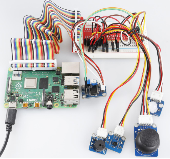
In this experiment, we will use some modules together to build an intelligent temperature measurement system.
Required Components
– 1 * Raspberry Pi
– 1 * Breadboard
– 1 * Active Buzzer
– 1 * RGB LED Module
– 1 * DS18B20 Temperature Sensor
– 1 * PCF8591
– 1 * Joystick PS2
– Several Jumper wires
Experimental Principle
It is similar with lesson 26. The only difference is that we can adjust the lower limit and upper limit value by joystick PS2 when programming.
As mentioned previously, joystick PS2 has five operation directions: up, down, left, right and press-down. Well, in this experiment, we will use the left and right directions to control the upper limit value and up/down direction to control the lower limit. If you press down the joystick, the system will log out.
Experimental Procedures
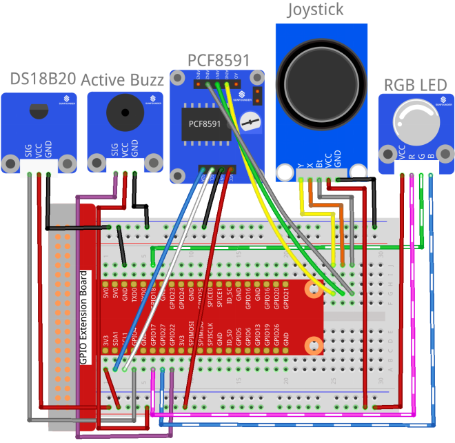
Step 1: Build the circuit.
| Raspberry Pi | GPIO Extension Board | DS18B20 Module |
| GPIO7 | GPIO4 | SIG |
| 3.3V | 3V3 | VCC |
| GND | GND | GND |
| Raspberry Pi | GPIO Extension Board | PCF8591 Module |
| SDA | SDA1 | SDA |
| SCL | SCL1 | SCL |
| 3.3V | 3V3 | VCC |
| GND | GND | GND |
| Joystick PS2 | GPIO Extension Board | PCF8591 Module |
| Y | * | AIN0 |
| X | * | AIN1 |
| Bt | * | AIN2 |
| VCC | 3V3 | * |
| GND | GND | * |
| Raspberry Pi | GPIO Extension Board | RGB LED Module |
| GPIO0 | GPIO17 | R |
| GPIO1 | GPIO18 | G |
| GPIO2 | GPIO27 | B |
| 3.3V | 3V3 | VCC |
| Raspberry Pi | GPIO Extension Board | Active Buzzer Module |
| GPIO3 | GPIO22 | SIG |
| 3.3V | 3V3 | VCC |
| GND | GND | GND |
For C Users:
Step 2: Check the address of your sensor.
ls /sys/bus/w1/devices/It may be like this:
28-031467805fff w1_bus_master1Copy or write down 28-XXXXXXX. It is the address of your sensor.
Step 2: Change directory and edit.
cd /home/pi/SunFounder_SensorKit_for_RPi2/C/35_expand02/
nano temp_monitor.c
Find the function float tempRead(void), and the line “fd = open(XXXXXX)”. Replace “28-031467805ff” with your sensor address.
float tempRead(void)
{
float temp;
int i, j;
int fd;
int ret;

char buf[BUFSIZE];
char tempBuf[5];

fd = open("/sys/bus/w1/devices/28-031467805fff/w1_slave", O_RDONLY);

if(-1 == fd){
perror("open device file error");
return 1;
}
Save and exit.
Step 4: Compile.
gcc temp_monitor.c -lwiringPiStep 5: Run.
sudo ./a.outFor Python Users:
Step 2: Change directory.
cd /home/pi/SunFounder_SensorKit_for_RPi2/Python/Step 4: Run.
sudo python3 35_temp_monitor.pyNow, you can pull the shaft of the joystick left and right to set the upper limit value, and up and down to set the lower limit value. Then, if the ambient temperature reaches the upper limit value or lower limit value, the buzzer will beep in a different frequency to warn.