Introduction
In this lesson, you will use PWM to control an RGB LED and cause it to display all kinds of colors.
Components
– 1 * RGB LED
– 3 * Resistor (220Ω)
– 1 * Breadboard
– 1 * SunFounder Uno board
– Jumper wires
– USB cable
Principle
RGB
RGB stands for the red, green, and blue color channels and is an industry color standard. RGB displays various new colors by changing the three channels and superimposing them, which, according to statistics, can create 16,777,216 different colors. If you say the color displayed doesn’t completely match a natural color, then it almost certainly cannot be differentiated with the naked eyes.
Each of the three color channels of red, green, and blue has 255 stages of brightness. When the three primary colors are all 0, “LED light” is the darkest, that is, it turns off. When the three primary colors are all 255, “LED light” is the brightest. When superimposing the light emitted by the three primary colors, the colors will be mixed. However, the brightness is equal to the sum of all brightness, and the more you mix, the brighter the LED is. This process is known as additive mixing.
In this experiment, we will also use PWM which, if you’ve followed the lessons thus far, you already have a basic understanding of. Here we input a value between 0 and 255 to the three pins of the RGB LED to make it display different colors.
Experimental Procedures
Step 1: Build the circuit
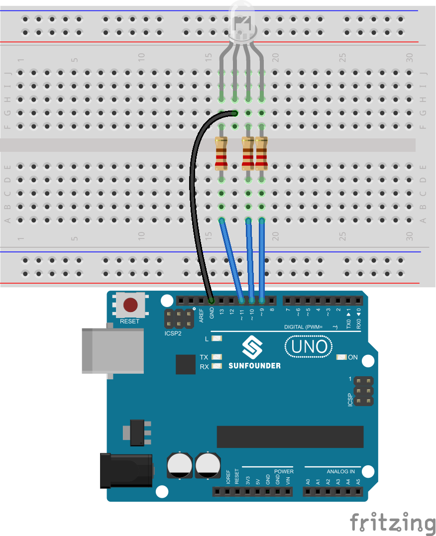
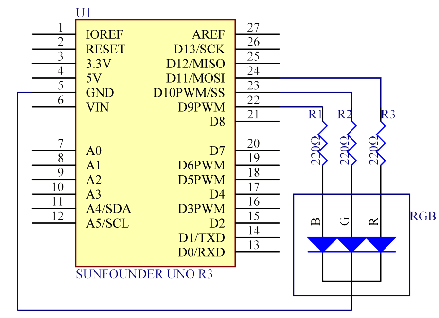
The schematic diagram
Step 2: Program (Please refer to the example code in LEARN -> Get Tutorials on our website)
Step 3: Compile the code
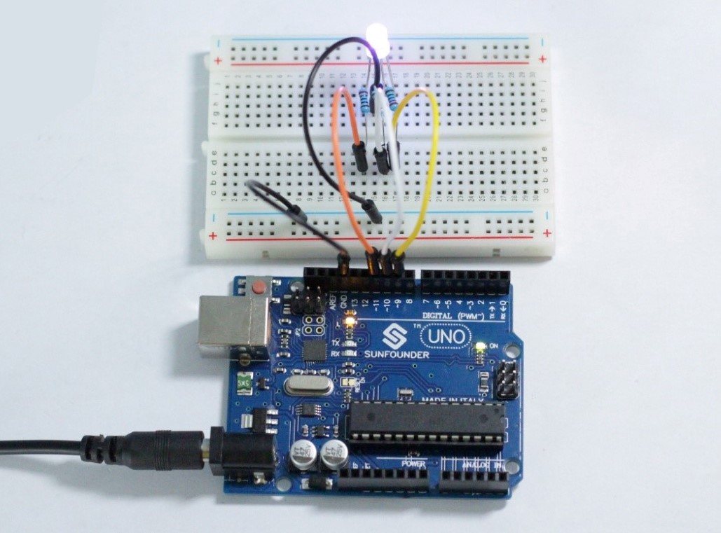
Step 4: Upload the sketch to the SunFounder Uno board
Here you should see the RGB LED flash circularly red, green, and blue first, then red, orange, yellow, green, blue, indigo, and purple.
Code
| //RGB LED //The RGB LED will appear red, green, and blue first, then red, orange, yellow, green, blue, indigo, and purple. //Email:support@sunfounder.com //Website:www.sunfounder.com //2015.5.7 /*************************************************************************/ const int redPin = 11; // R petal on RGB LED module connected to digital pin 11 const int greenPin = 10; // G petal on RGB LED module connected to digital pin 9 const int bluePin = 9; // B petal on RGB LED module connected to digital pin 10 /**************************************************************************/ void setup() { pinMode(redPin, OUTPUT); // sets the redPin to be an output pinMode(greenPin, OUTPUT); // sets the greenPin to be an output pinMode(bluePin, OUTPUT); // sets the bluePin to be an output } /***************************************************************************/ void loop() // run over and over again { // Basic colors: color(255, 0, 0); // turn the RGB LED red delay(1000); // delay for 1 second color(0,255, 255); // turn the RGB LED green delay(1000); // delay for 1 second color(0, 0, 255); // turn the RGB LED blue delay(1000); // delay for 1 second // Example blended colors: color(255,0,0); // turn the RGB LED red delay(1000); // delay for 1 second color(237,109,0); // turn the RGB LED orange delay(1000); // delay for 1 second color(255,215,0); // turn the RGB LED yellow delay(1000); // delay for 1 second color(34,139,34); // turn the RGB LED green delay(1000); // delay for 1 second color(0,0,255); // turn the RGB LED blue delay(1000); // delay for 1 second color(0,46,90); // turn the RGB LED indigo delay(1000); // delay for 1 second color(128,0,128); // turn the RGB LED purple delay(1000); // delay for 1 second } /******************************************************/ void color (unsigned char red, unsigned char green, unsigned char blue) // the color generating function { analogWrite(redPin, red); analogWrite(bluePin, blue); analogWrite(greenPin, green); } /******************************************************/ |
Video