Introduction
In this lesson, we will gradually increase and decrease the luminance of an LED with PWM (Pulse-width modulation) technology, which looks like breathing. So we give it a magical name – Breathing Light.
Experimental Conditions
– 1*Raspberry Pi
– 1*Breadboard
– 1*Network cable (or USB wireless network adapter)
– 1*LED
– 1*Resistor (220Ω)
– Jumper wires
Experimental Principle
Before we talk about PWM, let’s have a look at the applications of PWM first. PWM has been successfully applied in motor speed regulation, steering angle control, light intensity control and signal output. For example, when PWM is applied to a horn, it will make a sound. After we know about its special functions, let’s find out what PWM really is.
Pulse Width Modulation commonly refers to PWM. Pulse Width Modulation (PWM) is a digital coding method for analog signal levels. Since a computer cannot output an analog voltage but digital voltage value 0V or 3.3V, we modulate the duty cycle of square waves to encode a specific level of analog signal by using a high-resolution counter. PWM signals are essentially digital signals, for the full amplitude DC power supply is either 3.3V (ON) or 0V (OFF) at any given time. Voltage or current source is applied to an analog load in the form of ON or OFF repetitive pulse sequence. When it is on, DC power supply will be applied to the load; when it is off, DC power supply will be disconnected. If only the bandwidth is wide enough, any analog value can be encoded by PWM. The output voltage value is calculated by the on and off time, Vout = (Ton / T)*Vmax.
Here is the introduction to three basic parameters of PWM:

- The term duty cycle describes the proportion of ‘on’ time to the regular interval or ‘period’ of time
- The term period describes the reciprocal of pulses in one second
- Voltage amplitude (e.g. 0V-3.3V)
Experimental Procedures
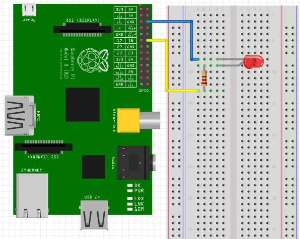
Step 1: Connect the circuit as shown in the following diagram
Step 2: Edit and save the code with vim (see path/Rpi_LcdStartKit /07_pwmLed/
pwmLed.c)
Step 3: Compile the code
| gcc PwmLed.c -lwiringPi |
Step 4: Run the program
| ./a.out |
Press Enter and you will see a gradual change of the LED luminance, rendering the effect of breathing.

Summary
Through this experiment, you should have mastered the technical principle of PWM and how to program Raspberry Pi with PWM. You can apply this technology to DC motor speed regulation in the future.
Code
| #include <wiringPi.h> #include <stdio.h> #define LedPin 1 int main(void) { int i; if(wiringPiSetup() == -1){ //when initialize wiring failed,print messageto screen printf(“setup wiringPi failed !”); return 1; } pinMode(LedPin, PWM_OUTPUT);//pwm output mode while(1){ for(i=0;i<1024;i++){ pwmWrite(LedPin, i); delay(2); } delay(1000); for(i=1023;i>=0;i–){ pwmWrite(LedPin, i); delay(2); } } return 0; } |