Introduction
The tilt switch used here is a ball one with a metal ball inside. It is used to detect inclinations of a small angle.
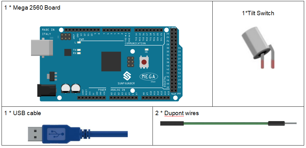
Components
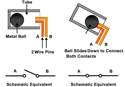
Experimental Principle
The principle is very simple. When the switch is tilted in a certain angle, the ball inside rolls down and touches the two contacts connected to the pins outside, thus triggering circuits. Otherwise the ball will stay away from the contacts, thus breaking the circuits.
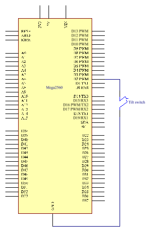
The schematic diagram:
Experimental Procedures
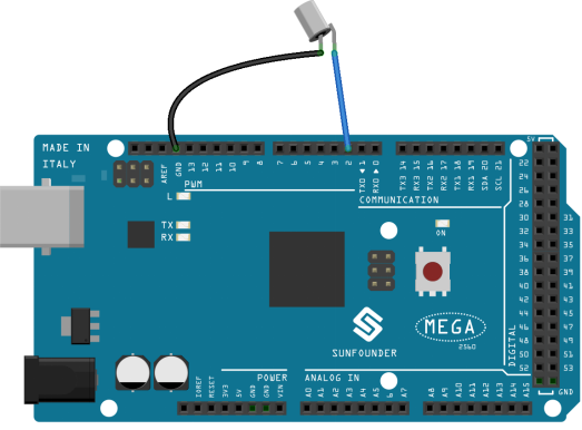
Step 1: Build the circuit
Step 2: Open the code file.
Step 3: Select the Board and Port.
Step 4: Upload the sketch to the board.
Now, tilt the switch, and the LED attached to pin 13 on Mega 2560 board will light up.

Code Analysis
Code Analysis 7-1 Whole Code
const int ledPin = 13;//the led attach to

void setup()
{
  pinMode(ledPin,OUTPUT);//initialize the ledPin as an output
  pinMode(2,INPUT);      //set pin2 as INPUT
  digitalWrite(2, HIGH); //set pin2 as HIGH
}
/******************************************/

void loop()
{
  int digitalVal = digitalRead(2);//Read the value of pin2
  if(HIGH == digitalVal)          //if tilt switch is not breakover
  {
    digitalWrite(ledPin,LOW);     //turn the led off
  }
  else                            //if tilt switch breakover
  {
    digitalWrite(ledPin,HIGH);    //turn the led on
  }
}
The whole code are very simple, one pin of the tilt switch is connected to pin2, another pin is connected to GND, when tilt the switch, the two pins of the switch will be connected to GND, then let the LED on the pin13 lights up.