Introduction
The 4N35 is an optocoupler for general purpose application. It consists of gallium arsenide infrared LED and a silicon NPN phototransistor. When the input signal is applied to the LED in the input terminal, the LED lights up. After receiving the light signal, the light receiver then converts it into electrical signal and outputs the signal directly or after amplifying it into a standard digital level. Thus, the transition and transmission of electricity-light-electricity is completed. Since light is the media of the transmission, meaning the input terminal and the output one are isolated electrically, this process is also be known as electrical isolation.
Components
-1 * 4N35
-1 * LED
-1 * 220 Ohm Resistor
– 1* 1k Ohm Resistor
– Some jump wires
Principle
4N35
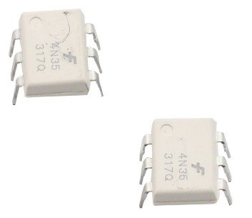
The 4N35 is an optocoupler for general purpose application. It consists of gallium arsenide infrared LED and a silicon NPN phototransistor.
What an optocoupler does is to break the connection between signal source and signal receiver, so as to stop electrical interference. In other words, it is used to prevent interference from external electrical signals. 4N35 can be used in AV conversion audio circuits. Broadly it is widely used in electrical insulation for a general optocoupler.
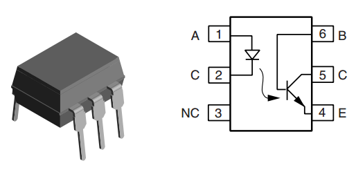
See the internal structure of 4N35 above. Pin 1 and 2 are connected to an infrared LED. When the LED is electrified, it’ll emit infrared rays. To protect the LED from burning, usually a resistor (about 1K) is connected to pin 1. Then the NPN phototransistor is power on when receiving the rays. This can be done to control the load connected to the phototransistor. Even when the load short circuit occurs, it won’t affect the control board, thus realizing good electrical isolation.
The schematic diagram:
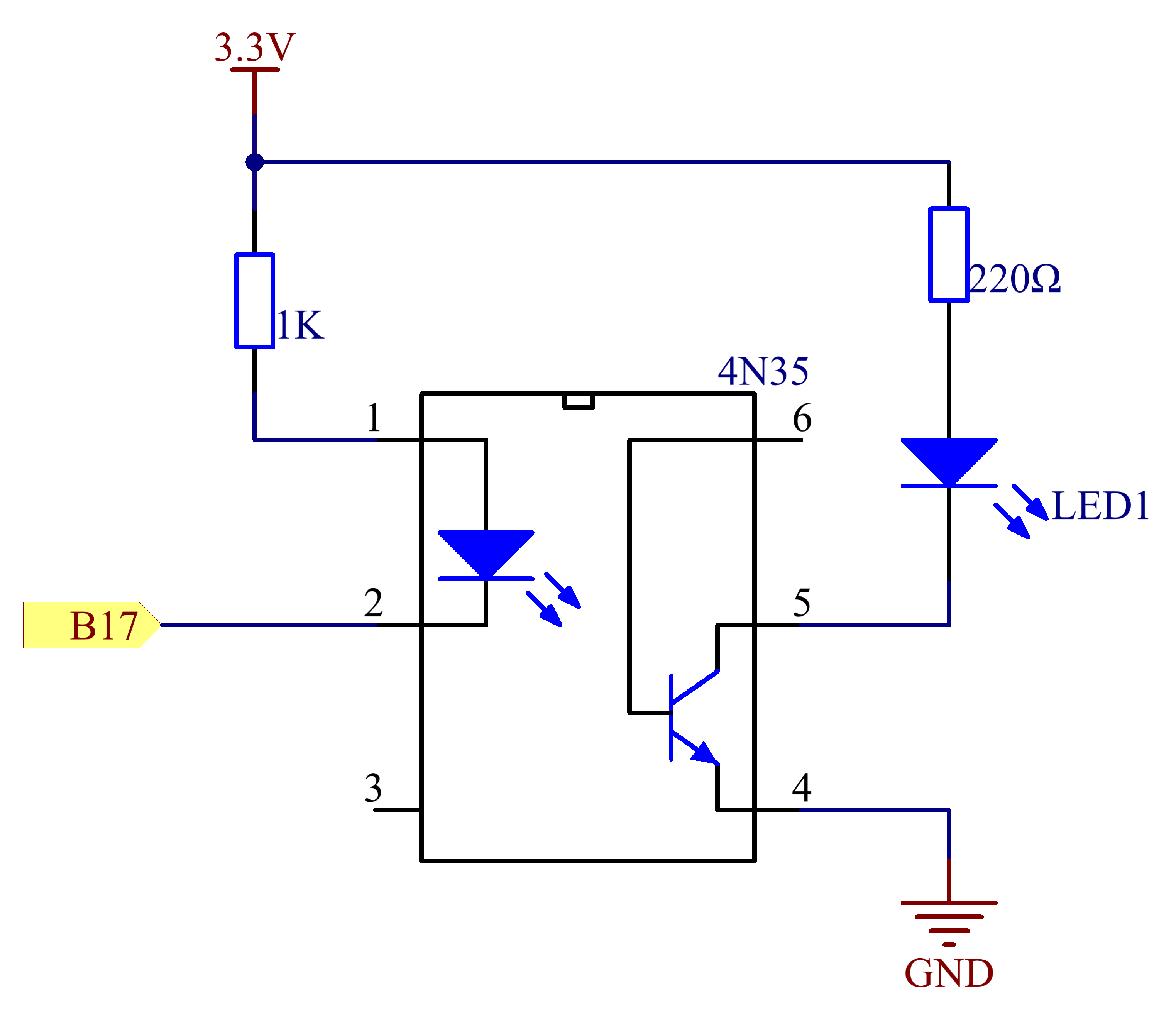
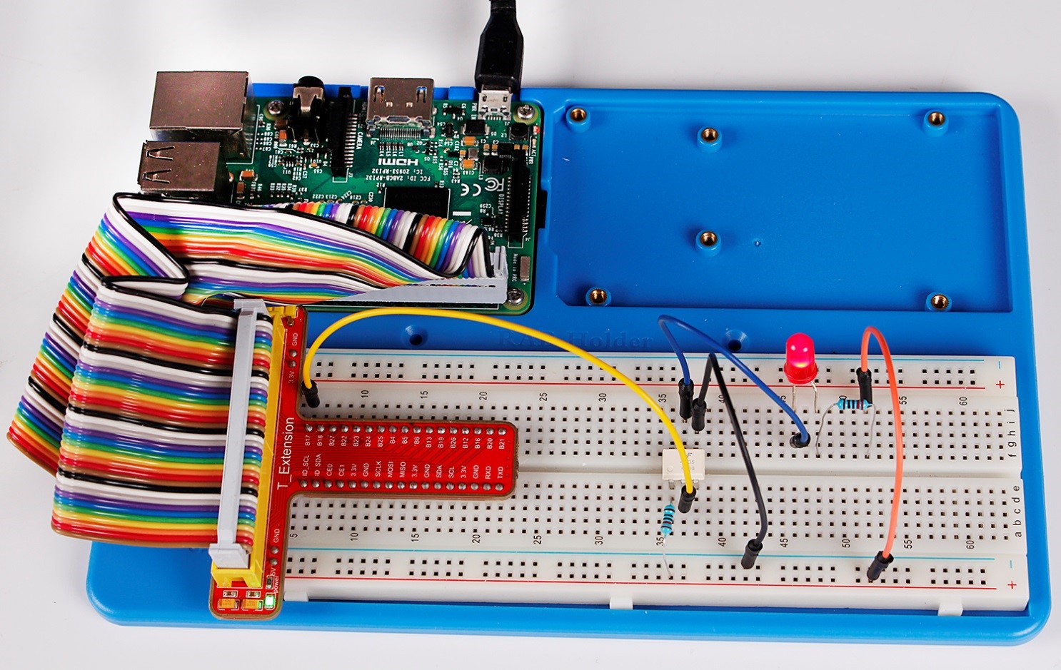
Principle: In this experiment, use an LED as the load connected to the NPN phototransistor. Connect pin 2 of 4N35 to pin B17, pin 1 connects a 1K current-limiting resistor and then a 3.3V. Connect pin 4 to GND, and pin 5 to the cathode of the LED. Then hook the anode of the LED to 3.3V after connecting with a 220 Ohm resistor. When in program, a LOW level is given to pin B17, the infrared LED will emit infrared rays. Then the phototransistor receives infrared rays and gets electrified, and the LED cathode is LOW, thus turning on the LED. Also you can control the LED by circuits only – connect pin 2 to ground and it will brighten.
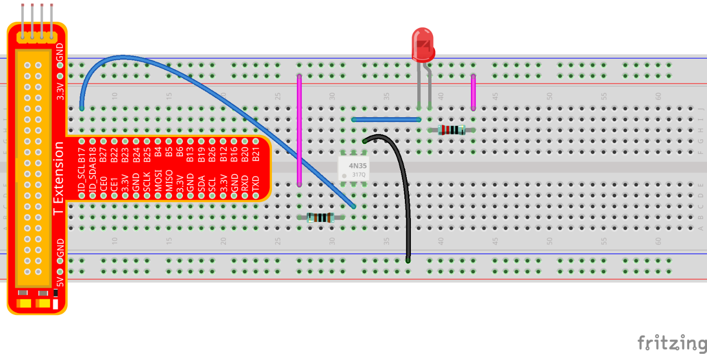
Step 1: Build the circuit
For C language users:
Step 2: Open the code file
cd /home/pi/SunFounder_Super_Kit_V3.0_for_Raspberry_Pi/C
Step 3: Compile the Code
make 08_4N35
Step 4: Run the executable file above.
sudo ./08_4N35
For Python users:
Step 2: Open the code file
cd /home/pi/SunFounder_Super_Kit_V3.0_for_Raspberry_Pi/Python
Step 3: Run
sudo python 08_4N35.py
You will see the LED blinks.
Exploration
4N35 is an optocoupler that usually used for driving relay as well as motor circuits. As there is no direct connection between the input and output, even if a short circuit at the output end occurs, the control board will not be burnt.Have a try!
C Code
/**********************************************************************
* Filename 		: 4N35.c
* Description 	: Make a 4N35 to contral led blinking
* Author 		: Dream
* E-mail 		: support@sunfounder.com
* Website 		: www.sunfounder.com
* Update 		: Dream    <2016-07-26>
* Detail		: <update details>
**********************************************************************/
#include <wiringPi.h>
#include <stdio.h>

#define _4N35Pin		0

int main(void)
{
	// When initialize wiring failed, print messageto screen
	if(wiringPiSetup() == -1){
		printf("setup wiringPi failed !");
		return 1;
	}

	pinMode(_4N35Pin, OUTPUT);

	printf("\n");
	printf("\n");
	printf("========================================\n");
	printf("|                 4N35                 |\n");
	printf("|    ------------------------------    |\n");
	printf("|      LED connect to 4N35 pin5;       |\n");
	printf("|      gpio0 connect to 4N35 pin2;    |\n");
	printf("|                                      |\n");
	printf("|     4N35 to contral led blinking.    |\n");
	printf("|                                      |\n");
	printf("|                            SunFounder|\n");
	printf("========================================");
	printf("\n");
	printf("\n");

	while(1){
		// LED on
		digitalWrite(_4N35Pin, LOW);
		printf("...LED on\n");
		delay(500);
		// LED off
		digitalWrite(_4N35Pin, HIGH);
		printf("LED off...\n");
		delay(500);
	}

	return 0;
}
Python Code
#!/usr/bin/env python

import RPi.GPIO as GPIO
import time

# Set #17 as 4N35 pin
Pin_4N35 = 17

# Define a function to print message at the beginning
def print_message():
	print ("========================================")
	print ("|                 4N35                 |")
	print ("|    ------------------------------    |")
	print ("|      LED connect to 4N35 pin5;       |")
	print ("|      gpio0 connect to 4N35 pin2;     |")
	print ("|                                      |")
	print ("|     4N35 to contral led blinking.    |")
	print ("|                                      |")
	print ("|                            SunFounder|")
	print ("========================================\n")
	print 'Program is running...'
	print 'Please press Ctrl+C to end the program...'
	raw_input ("Press Enter to begin\n")

# Define a setup function for some setup
def setup():
	# Set the GPIO modes to BCM Numbering
	GPIO.setmode(GPIO.BCM)
	# Set Pin_4N35's mode to output,
	# and initial level to High(3.3v)
	GPIO.setup(Pin_4N35, GPIO.OUT, initial=GPIO.HIGH)

# Define a main function for main process
def main():
	# Print messages
	print_message()
	while True:
		print '...LED ON'
		# Turn on LED
		GPIO.output(Pin_4N35, GPIO.LOW)
		time.sleep(0.5)
		print 'LED OFF...'
		# Turn off LED
		GPIO.output(Pin_4N35, GPIO.HIGH)
		time.sleep(0.5)

# Define a destroy function for clean up everything after
# the script finished
def destroy():
	# Turn off LED
	GPIO.output(Pin_4N35, GPIO.HIGH)
	# Release resource
	GPIO.cleanup()

# If run this script directly, do:
if __name__ == '__main__':
	setup()
	try:
		main()
	# When 'Ctrl+C' is pressed, the child program
	# destroy() will be  executed.
	except KeyboardInterrupt:
		destroy()