Introduction
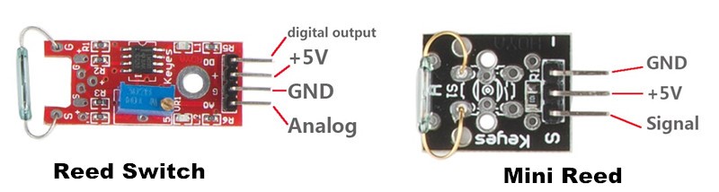
A reed switch (as shown below) is a sensor used to detect the magnetic field. Hall sensors are generally used to measure the speed of smart car and count products on assembly lines. Reed switches are often used to detect the existence of magnetic field.
There are two reed switches in this kit: reed switch and mini reed. They work in the same principle.
Components
– 1 * SunFounder Uno board
– 1 * USB data cable
– 1 * Reed switch module
– Several jumper wires
Experimental Principle
A reed switch is a type of line switch component that realizes control by magnetic signals. It induces by a magnet. The “switch” here means dry reed pipe, which is a kind of contact passive electronic switch component with the advantage of simple structure, small size, and convenient control. The shell of a reed switch is commonly a sealed glass pipe in which two iron elastic reed electroplates are equipped and inert gases are filled.
Normally, the two reeds made of special materials in the glass tube are separated. However, when a magnetic substance approaches the glass tube, the two reeds in the glass tube are magnetized to attract each other and get touched due to the magnetic force. As a result, the two reeds close the circuit connected with the nodes.
After the external magnetic force disappears, the two reeds will be separated with each other again because their like poles are placed near which intend to repel them apart, thus breaking the circuit. Therefore, as line switch components function by magnetic signals, they can be used to count stuff, restrict positions and so on. At the same time, it is widely used in a variety of communication devices.
In this experiment, since an LED has been attached to pin 13, just connect pin D0 of the reed switch to D8 of the SunFounder Uno board. When the reed switch inducts magnetic field signals, the LED will be on. Otherwise, it will be off.
Experimental Procedures
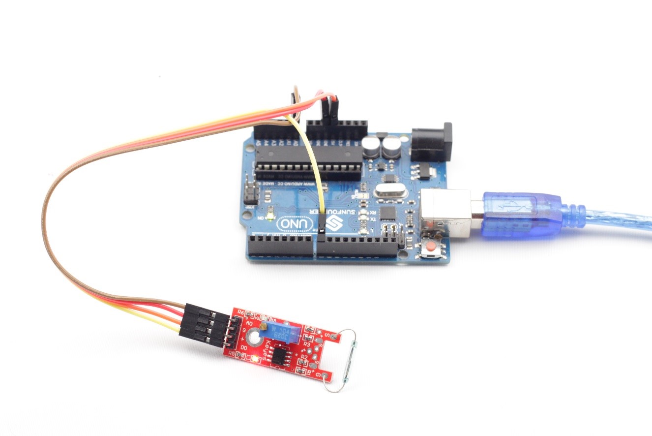
Step 1: Build the circuit
Reed Switch Module SunFounder Uno
AO —————————————- A0
DO —————————————-D8
– —————————————– GND
+ —————————————— 5V
Step 2: Program (Please refer to the example code in LEARN -> Get Tutorial on our website)
Step 3: Compile
Step 4: Upload the sketch to SunFounder Uno
Now, put a magnet close to the reed switch, and you will see the LED attached to pin 13 on the SunFounder Uno board light up.
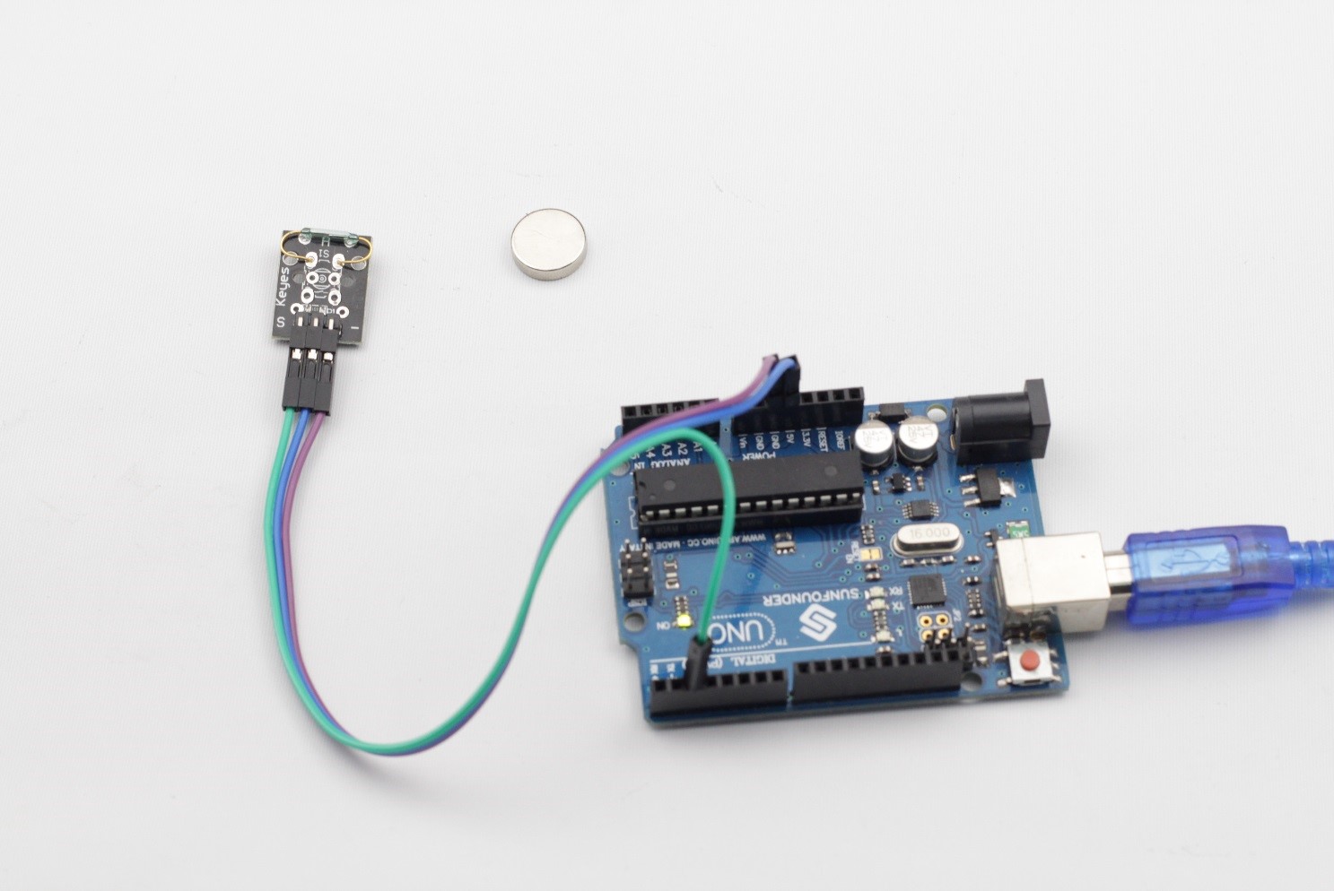
Mini Reed
The experimental procedures are the same as those of Reed Switch. Connect pin S to D2 of the SunFounder board, and you will see the LED attached to pin 13 light up when a magnet approaches the mini reed.
C Code for Mini Reed
| const int buttonPin = 2; // the number of the pushbutton pin const int ledPin = 13; // the number of the LED pin// variables will change: int buttonState = 0; // variable for reading the pushbutton statusvoid setup() { // initialize the LED pin as an output: pinMode(ledPin, OUTPUT); // initialize the miniReed pin as an input: pinMode(buttonPin, INPUT); }void loop(){ // read the state of the mini reed : buttonState = digitalRead(buttonPin); if (buttonState == HIGH) { // turn LED off: digitalWrite(ledPin, LOW); } else { // turn LED on: digitalWrite(ledPin, HIGH); } } |
C Code for Reed Switch
| const int analogInPin = A0; const int digitalInPin = 8; const int ledPin = 13;void setup() { pinMode(digitalInPin,INPUT); pinMode(ledPin,OUTPUT); }void loop() { int analogVal = analogRead(analogInPin); boolean stat = digitalRead(digitalInPin); if(stat == HIGH) { digitalWrite(ledPin,HIGH); } else { digitalWrite(ledPin,LOW); } } |