Introduction
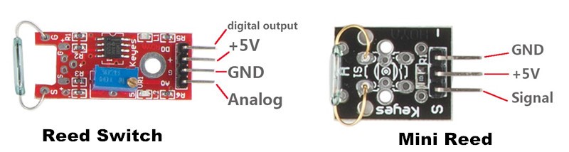
A reed switch (as shown below) is also a sensor used to detect a magnetic field. Hall sensors are generally used to measure intelligent vehicle speed and count products on assembly lines, when reed switches are often to detect the existence of magnetic field.
There are two kinds of reed switch in this kit: reed switch and mini reed. They share the same principle.
Components
– 1 * Raspberry Pi
– 1 * Breadboard
– 1 * Network cable (or USB wireless network adapter)
– 1 * Reed switch module
– 1 * Mini reed module
– 1 * Dual-color Common-Cathode LED module
– Several jumper wires
Experimental Principle
A reed switch is a type of line switch component that realizes control by magnetic signals. It induces by a magnet. The “switch” here means dry reed pipe, which is a kind of contact passive electronic switch component with the advantage of simple structure, small size, and convenient control. The shell of a reed switch is commonly a sealed glass pipe in which two iron elastic reed electroplates are equipped and inert gases are filled.
Normally, the two reeds made of special materials in the glass tube are separated. However, when a magnetic substance approaches the glass tube, the two reeds in the glass tube are magnetized to attract each other and get touched due to the magnetic force. As a result, the two reeds close the circuit connected with the nodes.
After the external magnetic force disappears, the two reeds will be separated with each other again because their like poles are placed near which intend to repel them apart, thus breaking the circuit. Therefore, as line switch components function by magnetic signals, they can be used to count stuff, restrict positions and so on. At the same time, it is widely used in a variety of communication devices.
Experimental Procedures
For Reed Switch
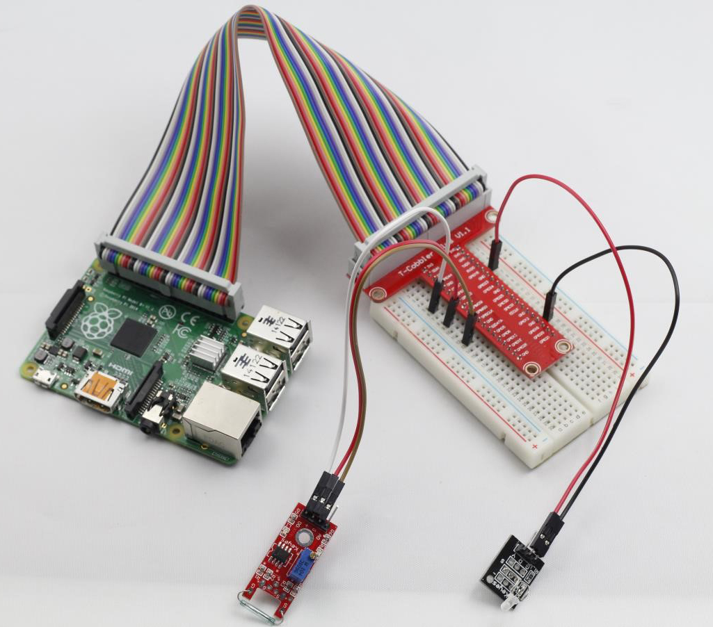
Step 1: Build the circuit
Reed switch connection: connect pin DO on Reed switch module to GPIO0 on Raspberry Pi; GND to GND; pin + to 3.3V
Raspberry Pi Reed Switch
GPIO0 ————————————- DO
3.3V ————————————— +
GND ————————————— G
Dual-color LED module connection: connect pin S of the dual-color LED module to GPIO1 on Raspberry Pi; GND to GND; pin + to 3.3V
Raspberry Pi Dual-color LED
GPIO1 ————————————- S
3.3V ————————————— +
GND ————————————– –
Step 2: Edit and save the code (see path/Rpi_SensorKit_code/10_magicRing/magicRing.c)
Step 3: Compile
gcc magicRing -lwiringPi
Step 4: Run
./a.out
Put a magnet close to the reed switch. Then pin DO will output high level, “Detected Magnetic Material” will be displayed on the screen and the dual-color LED will light up.
For Mini Reed
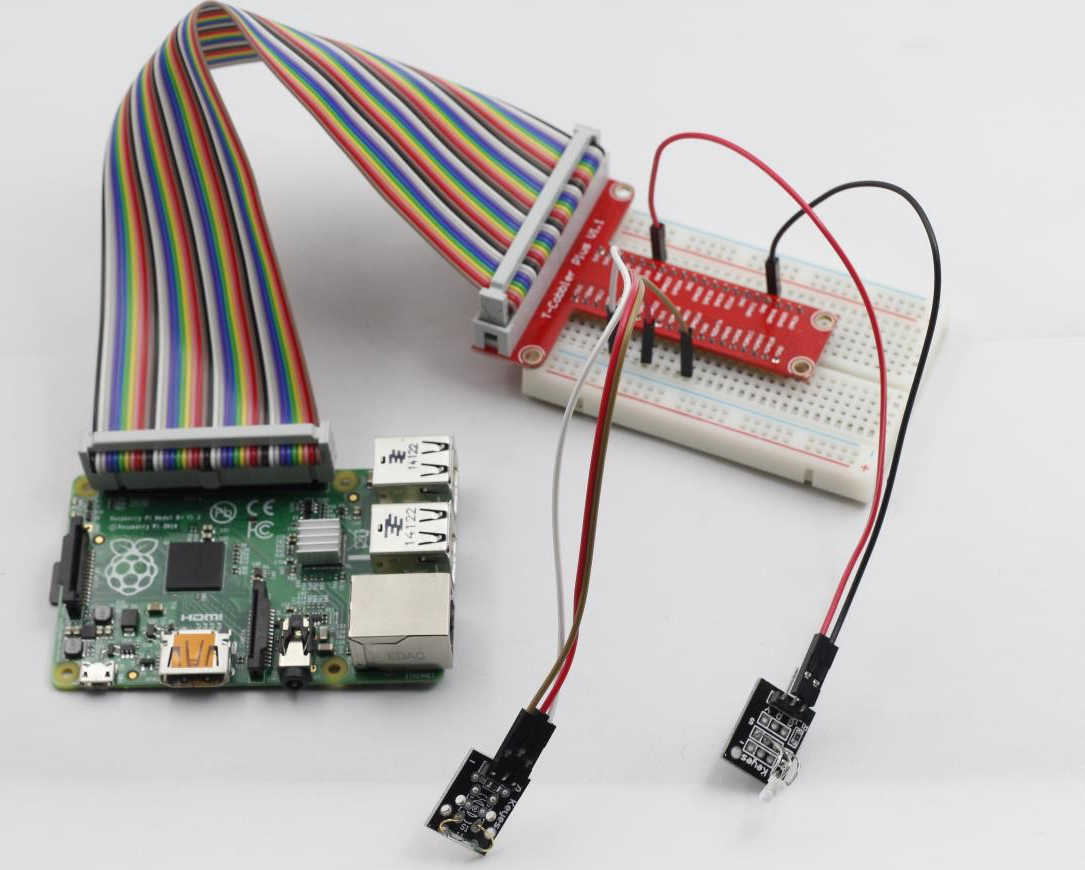
Step 1: Build the circuit
Same connections with Reed switch except pin S of Mini Reed to GPIO0 of Raspberry Pi.
Step 2: Edit and save the code (see path/Rpi_SensorKit_code/10_magicRing/magicRing.c)
Step 3: Compile
gcc magicRing.c -lwiringPi
Step 4: Run
./a.out
Then you’ll see the similar result to that of the reed switch.
magicRing.c
#include <wiringPi.h>
#include <stdio.h>

#define SwitchPin         0
#define LedPin            1

int main(void)
{
	if(wiringPiSetup() == -1){ //when initialize wiring failed,print messageto screen
		printf("setup wiringPi failed !");
		return 1;
	}

	pinMode(SwitchPin, INPUT);
	pinMode(LedPin,  OUTPUT);

	while(1){
		if(digitalRead(SwitchPin) == LOW){
			printf("on !\n");
			digitalWrite(LedPin, HIGH);     //led on
		}
		else{
			printf("off !\n");
			digitalWrite(LedPin, LOW);
		}
	}

	return 0;
}
Python Code
#!/usr/bin/env python
import RPi.GPIO as GPIO

ReedPin = 11
LedPin  = 12

def setup():
	GPIO.setmode(GPIO.BOARD)       # Numbers GPIOs by physical location
	GPIO.setup(LedPin, GPIO.OUT)   # Set LedPin's mode is output
	GPIO.setup(ReedPin, GPIO.IN, pull_up_down=GPIO.PUD_UP)
	GPIO.output(LedPin, GPIO.LOW) # Set LedPin high(+3.3V) to off led

def switchLed(channel):
	if GPIO.input(11):
		print "Magnet detected - LED on!"
		GPIO.output(LedPin,GPIO.HIGH)
	else:
		print "No magnet detected - LED off!"
		GPIO.output(LedPin,GPIO.LOW)

def loop():
	GPIO.add_event_detect(ReedPin,GPIO.BOTH, callback=switchLed, bouncetime=20)
	while True:
        	pass

def destroy():
	GPIO.output(LedPin, GPIO.LOW)     # led off
	GPIO.cleanup()                     # Release resource

if __name__ == '__main__':     # Program start from here
	setup()
	try:
		loop()
	except KeyboardInterrupt:  # When 'Ctrl+C' is pressed, the child program destroy() will be  executed.
		destroy()