Introduction
As we may know, relay is a device which is used to provide connection between two or more points or devices in response to the input signal applied. In other words, relays provide isolation between the controller and the device as devices may work on AC as well as on DC. However, they receive signals from a micro-controller which works on DC hence requiring a relay to bridge the gap. Relay is extremely useful when you need to control a large amount of current or voltage with small electrical signal.
Components
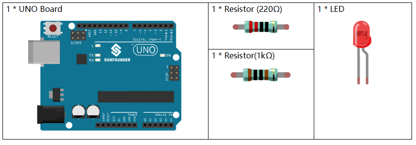
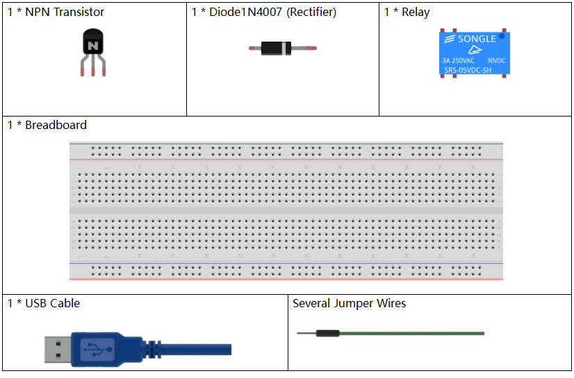
Component Introduction
Relay
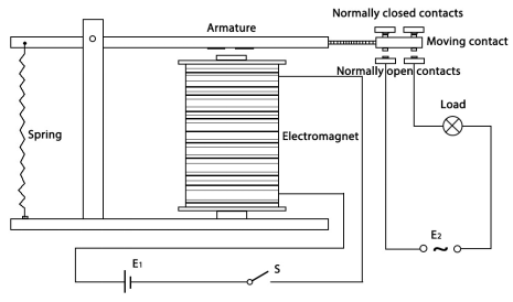
There are 5 parts in every relay:
1. Electromagnet – It consists of an iron core wounded by coil of wires. When electricity is passed through, it becomes magnetic. Therefore, it is called electromagnet.
2. Armature – The movable magnetic strip is known as armature. When current flows through them, the coil is it energized thus producing a magnetic field which is used to make or break the normally open (N/O) or normally close (N/C) points. And the armature can be moved with direct current (DC) as well as alternating current (AC).
3. Spring – When no currents flow through the coil on the electromagnet, the spring pulls the armature away so the circuit cannot be completed.
4. Set of electrical contacts – There are two contact points:
. Normally open – connected when the relay is activated, and disconnected when it is inactive.
. Normally close – not connected when the relay is activated, and connected when it is inactive.
5. Molded frame – Relays are covered with plastic for protection.
Working of Relay
The working principle of relay is simple. When power is supplied to the relay, currents start flowing through the control coil; as a result, the electromagnet starts energizing. Then the armature is attracted to the coil, pulling down the moving contact together thus connecting with the normally open contacts. So the circuit with the load is energized. Then breaking the circuit would a similar case, as the moving contact will be pulled up to the normally closed contacts under the force of the spring. In this way, the switching on and off of the relay can control the state of a load circuit.
Transistor
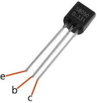
Transistor is a semiconductor device that controls current by current. It functions by amplifying weak signal to larger amplitude signal and is also used for non-contact switch. A transistor is a three-layer structure composed of P-type and N-type semiconductors. They form the three regions internally. The thinner in the middle is the base region; the other two are both N-type or P-type ones – the smaller region with intense majority carriers is the emitter region, when the other one is the collector region. This composition enables the transistor to be an amplifier.
From these three regions, three poles are generated respectively, which are base (b), emitter (e), and collector (c). They form two P-N junctions, namely, the emitter junction and collection junction. The direction of the arrow in the transistor circuit symbol indicates that of the emitter junction. Based on the semiconductor type, transistors can be divided into two groups, the NPN and PNP ones. From the abbreviation, we can tell that the former is made of two N-type semiconductors and one P-type and that the latter is the opposite. See the figure below.
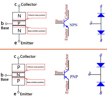
When a High level signal goes through an NPN transistor, it is energized. But a PNP one needs a Low level signal to manage it. Both types of transistor are frequently used for contactless switches, just like in this experiment.
Schematic Diagram
Connect a 1K resistor (for current limiting when the transistor is energized) to pin 8 of the SunFounder Uno board, then to an NPN transistor whose collector is connected to the coil of a relay and emitter to GND; connect the normally open contact of the relay to an LED and then GND. Therefore, when a High level signal is given to pin 8, the transistor is energized, thus making the coil of the relay conductive. Then its normally open contact is closed, and the LED will light up. When pin 8 is given a Low level, the LED will stay dim.
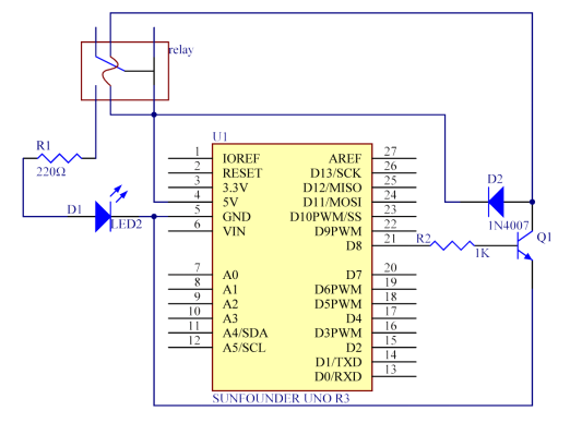
Function of the freewheeling diode: When the voltage input changes from High (5V) to Low (0V), the transistor changes from saturation (three working conditions: amplification, saturation, and cut-off) to cut-off, the current in the coil suddenly has no way to flow through. At this moment, without the freewheeling diode, a counter-electromotive force (EMF) will be generated at the ends of the coil, with positive at the bottom and negative at the top, a voltage higher than 100V. This voltage plus that from the power at the transistor are big enough to burn it. Therefore, the freewheeling diode is extremely important in discharging this counter-EMF in the direction of the arrow in the figure above, so the voltage of the transistor to GND is no higher than +5V (+0.7V).
In this experiment, when the relay closes, the LED will light up; when the relay opens, the LED will go out.
Experimental Procedures
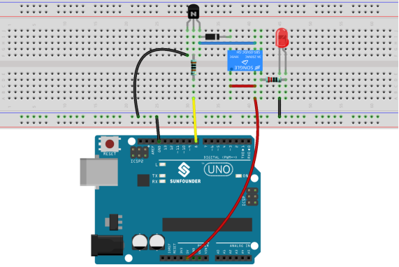
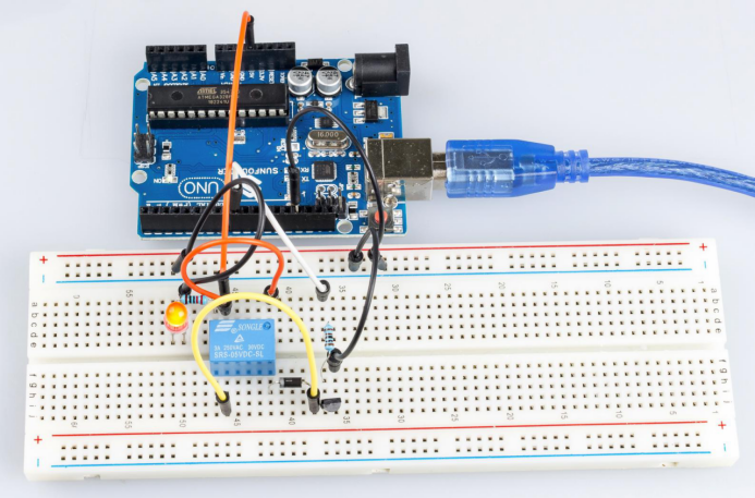
Step 1: Build the circuit
Step 2: Open the code file.
Step 3: Select the Board and Port.
Step 4: Upload the sketch to the board.
Now, send a High level signal, and the relay will close and the LED will light up; send a low one, and it will open and the LED will go out. In addition, you can hear a tick-tock caused by breaking the normally close contact and closing the normally open one.
Code Analysis
void loop()
{
digitalWrite(relayPin, HIGH); //drive relay closure conduction
delay(1000); //wait for a second
digitalWrite(relayPin, LOW); //drive the relay is closed off
delay(1000); //wait for a second
}
The code in this experiment is simple. First, set relayPin as HIGH level and the LED connected to the relay will light up. Then set relayPin as LOW level and the LED goes out.