Introduction
The NE555 Timer, a mixed circuit composed of analog and digital circuits, integrates analog and logical functions into an independent IC, thus tremendously expanding the applications of analog integrated circuits. It is widely used in various timers, pulse generators, and oscillators. In this lesson, we will learn how to use the 555 timer.
Components
– 1 * Raspberry Pi
– 1 * Breadboard
– 1 * NE555
– 3 * Resistor (1 * 1KΩ, 2 * 10KΩ)
– 2 * Capacitor (100nF)
– Jumper wires
Principle
555 IC
A 555 timer is a medium-sized IC device which combines analog and digital functions. With low cost and reliable performance, it just attaches external resistors and capacitors so as to achieve the functions of multivibrator, monostable trigger, Schmitt trigger and other circuits which can generate and transform pulses. It is also used frequently as a timer and widely applied to instruments, household appliances, electronic measurement, automatic control and other fields.
Its pins and their functions:
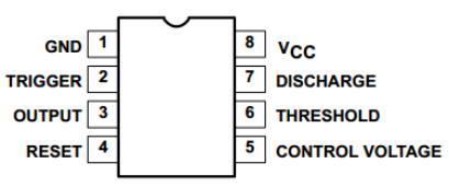
As shown in the picture, the pins are set dual in-line with the 8-pin package.
- Pin 1 (GND): the ground
- Pin 2 (TRIGGER ): the input of lower comparator
- Pin 3 (OUTPUT): having two states of 0 and 1 decided by the input electrical level
- Pin 4 (RESET): outputting low level when supplied a low one
- Pin 5 (CONTROL VOLTAGE): changing the upper and lower level trigger values
- Pin 6 (THRESHOLD): the input of the upper comparator
- Pin 7 (DISCHARGE): having two states of suspension and ground connection also decided by the input, and the output of the internal discharge tube
- Pin 8 (VCC): the power supply
The 555 timer can work under three modes. In this experiment, the astable mode is used to generate square waves.
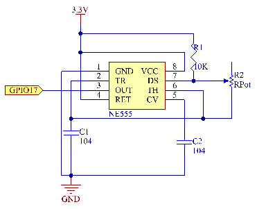
Under the astable mode, the frequency of output waveform of the 555 timer is determined by R1, R2 and C2:
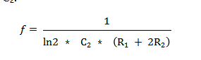
In the above circuit, R1= R2=10KΩ=Ω;
=100nF=
F, so we can get the frequency:
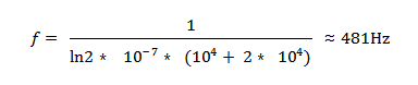
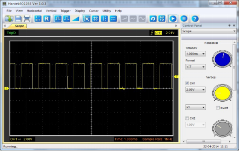
After connecting the circuit according to the schematic diagram, use an oscilloscope to observe the frequency of the output waveform. We can see it is consistent with the above calculated result.
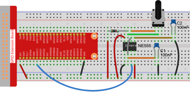
Attach the output pin (e.g. pin 3) of the 555 timer to GPIO17 of the Raspberry Pi, configure GPIO17 as the mode of the rising edge interrupt by programming, and then detect the square wave pulses generated by the 555 timer with interrupt. The work of Interrupt Service Routine (ISR) is to add 1 to a variable.
Experimental Procedures
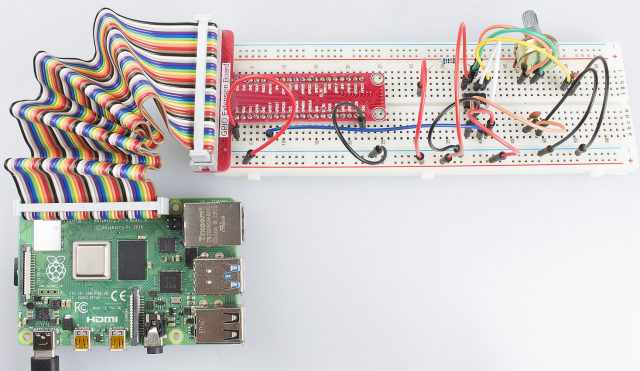
Step 1: Build the circuit.
For C Language Users:
Step 2: Change directory.
cd /home/pi/Sunfounder_SuperKit_C_code_for_RaspberryPi/09_Timer555/ Step 3: Compile.
gcc timer555.c -o timer555 -lwiringPiStep 4: Run.
sudo ./timer555For Python Users:
Step 2: Change directory.
cd /home/pi/Sunfounder_SuperKit_Python_code_for_RaspberryPi/Step 3: Run.
sudo python3 09_timer555.pyNow, you should see data printed on the display, which are square waves generated by the 555 timer. The program counts pulses by interrupt as we have learned previously.