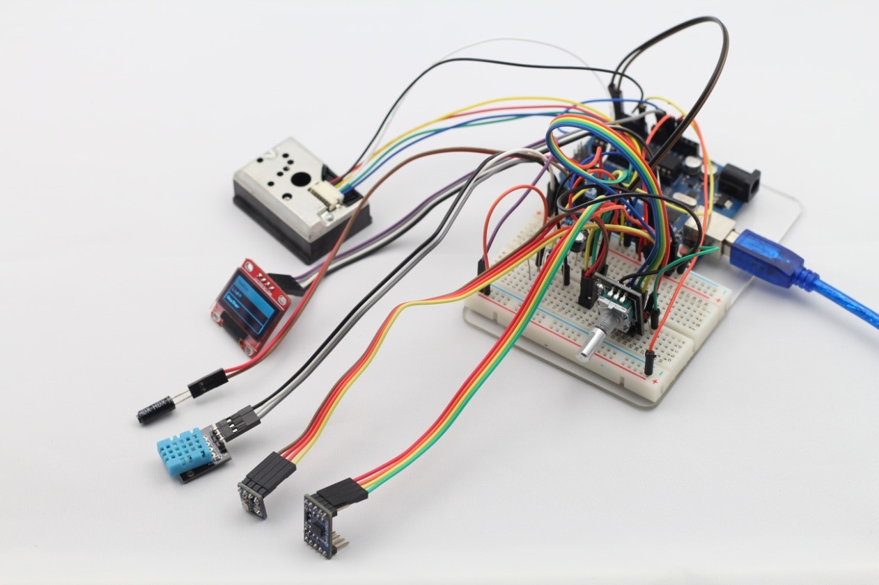
Overview
In this kit, we will learn how to use the OLED and all kinds of sensors and how to use them together. The sensors we will use include temperature and humidity DHT11, photoresistor, 3-axis accelerometer ADXL345, tilt switch, air pressure sensor BMP085, and dust sensor GP2Y1010AU0F (can test the current value of PM2.5). We will also use rotary encoder, and, of course, our protagonist OLED (0.96 inch).
Introduction to Sensors
Photoresistor
A photoresistor (see Figure 1) gets it resistance from the light. If it is dark, the sensor will read up in the millions of Ohms, but as light shines at it, it will have a lower resistance. The sensor requires a voltage divider to get a correct signal.
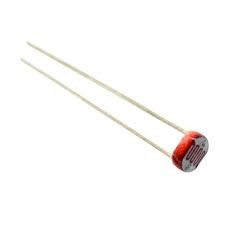
Figure 1. Photoresistor
Tilt Sensor
The tilt sensor (see Figure 2) is used to check whether or not something is level. It has a small metal ball inside the cap; when it is tilted, the ball connects with the outer cylinder and sends HIGH to the SunFounder Uno. This sensor acts like a switch and requires a pull-up resistor.
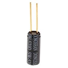
Figure 2. Tilt Sensor
DHT11
The DHT11 sensor shown in Figure 3 can detect temperature (C and F) and humidity. It has everything it requires built into it, so it will work very well with the SunFounder Uno. This sensor is used in conjunction with the DHT11 library.
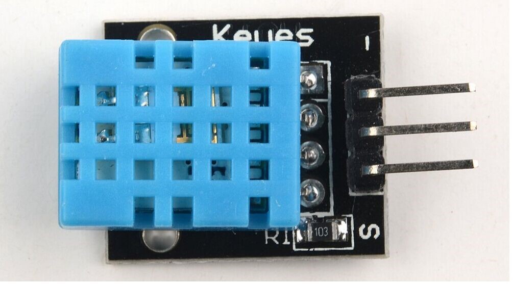
Figure 3. DHT11
ADXL345
The ADXL345 is a small, thin, ultra-low power, 3-axis accelerometer with high resolution (13-bit) measurement at up to ±16 g. Digital output data is formatted as 16-bit twos complement and is accessible through either a SPI (3-or 4-wire) or I2C digital interface.
The ADXL345 is well suited for mobile device applications. It measures the static acceleration of gravity in tilt-sensing applications, as well as dynamic acceleration resulting from motion or shock. Its high resolution (3.9mg/LSB) enables measurement of inclination changes less than 1.0°.
It provides several special sensing functions. Activity and inactivity sensing detect the presence or lack of motion by comparing the acceleration on any axis with user-set thresholds. Tap sensing detects single and double taps in any direction. Free-fall sensing detects if the device is falling. These functions can be mapped individually to either of two interrupt output pins. An integrated, patent pending memory management system with a 32-level first in, first out (FIFO) buffer can be used to store data to minimize host processor activity and lower overall system power consumption.
Low power modes enable intelligent motion-based power management with threshold sensing and active acceleration measurement at extremely low power dissipation.
The ADXL345 is supplied in a small, thin, 3 mm × 5mm × 1mm, 14-lead, plastic package.
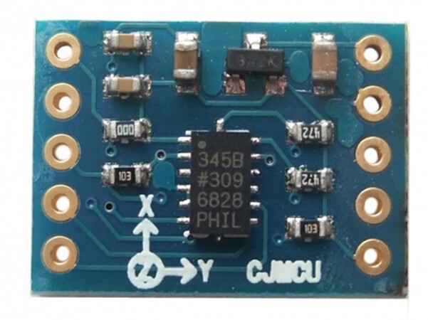
Figure 4. ADXL345
BMP180
The BMP180 (see Figure 5) is designed to be connected directly to a microcontroller of a mobile device via the I2C bus. The pressure and temperature data has to be compensated by the calibration data of the E2PROM of the BMP180.
The BMP180 consists of a piezo-resistive sensor, an analog to digital converter and a control unit with E2PROM and a serial I2C interface. In this tutorial, we use Adafruit_BMP085_Unified and adafruit_sensor_maste libraries to read the value of BMP180.
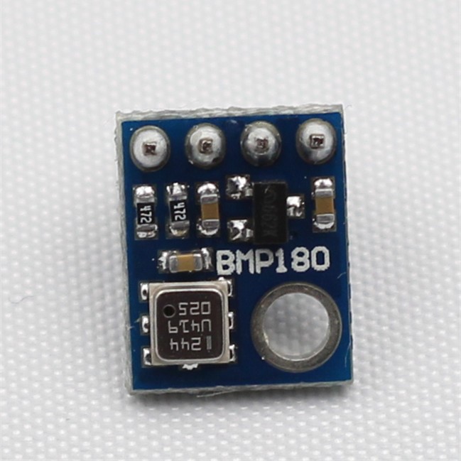
Figure 5. BMP180
GP2Y1010AU0F
Optical dust sensor (GP2Y1010AU0F) (as shown in figure 6) manufactured by Sharp can effectively detect smoke and indoor dust and other dust in the air. An infrared light-emitting diode and a phototransistor are diagonally placed in the sensor, which are used to detect the reflected light of dust in the air. Sensor signals are output in the form of analog voltage that is proportional to the dust concentration. The SunFounder Uno board reads the analog voltage with analog port to get the concentration of dust in the air after proper conversion.
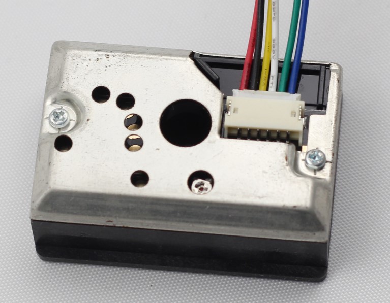
Figure 6. GP2Y1010AU0F
Rotary Encoder
A rotary encoder (see figure 7) is a kind of photoelectric sensor, which is used to detect mechanical movement and displacement, and convert them into electrical signals. It transforms analog signals into digital signals produced by shaft rotation through internal fixed circuit to determine the position, speed and angle in the automation system. Rotary encoder has single channel output and dual channel output. Here we use dual channel output rotary encoder to output two groups A/B pulses with phase difference of 90 degrees. SunFounder Uno judges the rotation direction and angle by reading the two groups of pulses.
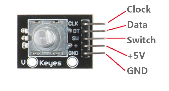
Figure 7. Rotary Encoder
OLED
OLED (Organic Light Emitting Diode) (as shown in figure 8) display technology features self-luminous. It uses very thin organic materials coating and glass substrates. When there is current flowing through the organic material, it will glow. In addition, OLED display screen has large viewing angle and can save power. The characteristics of OLED technology are as follows:
1. The OLED device has very thin core layer, whose thickness can be less than 1 mm, just a third of the LCD.
2. The OLED device has all solid state structure without the vacuum and liquid material, thus has good earthquake resistance, and can adapt to the huge acceleration, vibration and other bad environment.
3. The self-luminous characteristic makes the OLED almost no limitation of the angle of view, which generally can reach 170 degrees. With a broad perspective, no distortion even you see from the side.
4. The response time of the OLED display screen is shorter than that of TFT-LCD screen, which is about tens of milliseconds, now the response time of the best TFT – LCD is only 12 milliseconds. But the response time of the OLED display is about a few microseconds to tens of microseconds.
5. With good low temperature performance, the OLED can display normally even under minus 40 degrees Celsius. It is also used as a display screen in space suit at present. However, the response speed of the TFT-LCD changes with temperature. Under low temperature, it slows down. Therefore, the LCD has bad display effect under low temperature.
6. The OLED uses the principle of organic light-emitting, requires only a few materials and less production processes (less than 3 processes) corresponding to the production process of LCD. Therefore, the cost is greatly reduced.
7. The OLED uses a self-luminous diode, therefore does not need back light source. With high luminous conversion efficiency and lower energy consumption than LCD, the OLED can be manufactured on different material of substrate, whose circuit even can be printed on the elastic material – make it bendable soft display.
8. The OLED uses low voltage (under 5v) DC to drive, can be lit with batteries. With high brightness, it can reach above 300lm.
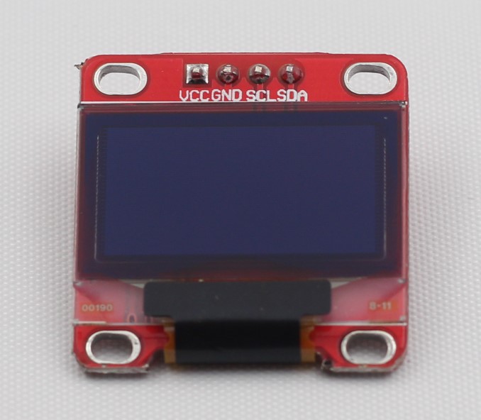
Figure 8. OLED
Experiment
Experiment 1 Using an OLED to Display a Picture
Overview:
In this routine, we will learn how to use an OLED to display a simple picture. This requires you modulo the picture that you want to display. Here we use special modulus software to complete this process.
Components:
SunFounder Uno R3 * 1
0.96 Inch OLED * 1
USB Data Cable * 1
Jumper Wires
Steps:
First, connect the circuit
SunFounder Uno OLED
SCL —————————— SCL
SDA —————————– SDA
3.3V —————————– VCC
GND —————————– GND
Second, generate a 128*64 pixels picture with .bmp format (you can also generate a random less than 128 * 64 pixels image, here we take 128 * 64 pixels image for example) by Photoshop or other similar software, as shown in figure 9.

Figure 9
Open the modulus software we provide, you will see the following picture as shown in figure 10.
Figure 10
Click the icon in the red box on the left to open the previously generated picture, as shown in figure 11:
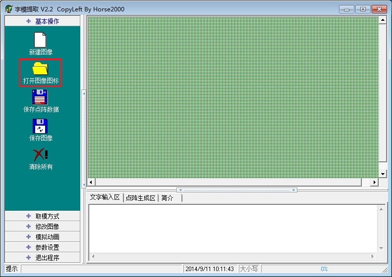
Figure 11
After opened, as shown in figure 12:
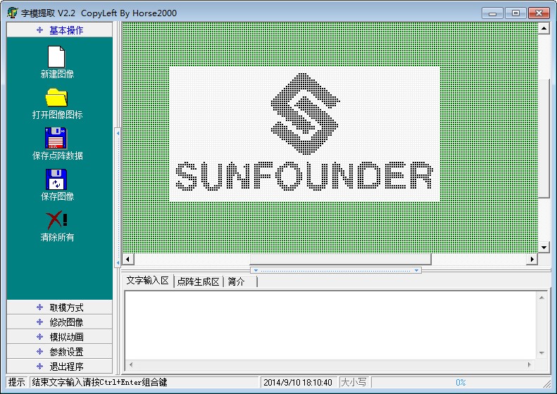
Figure 12
Click the option in the red box on the left to select modulus method, as shown in figure 13:
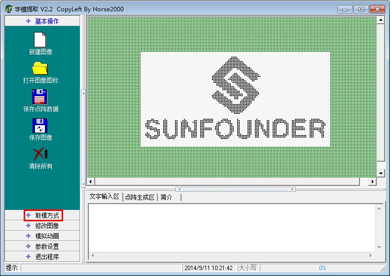
Figure 13
Now, the following picture will appear, as shown in figure 14:
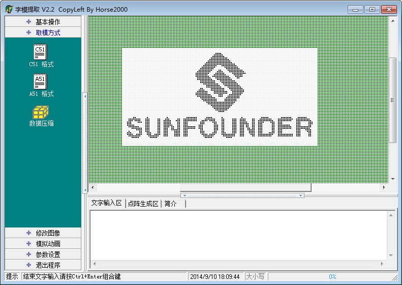
Figure 14
Click the option in the red box on the left to select C51 format, as shown in figure 15:
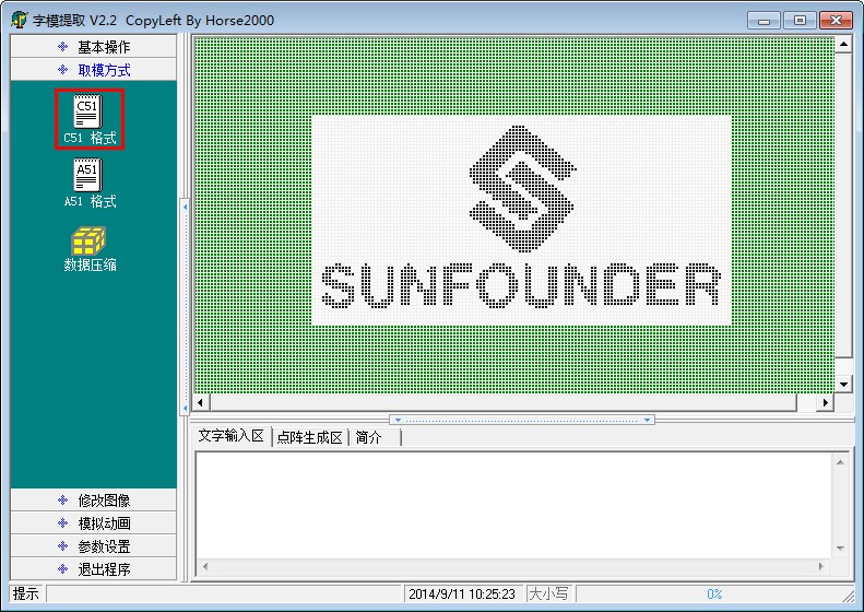
Figure 15
Now, you will see the following picture, the contents in the red box display generated code.
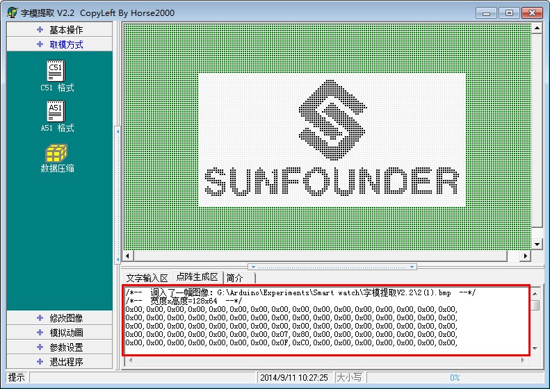
Figure 16
Paste the code as shown in figure 17 to ”bitmap.h” in code ”picture” we provide, save and exit.
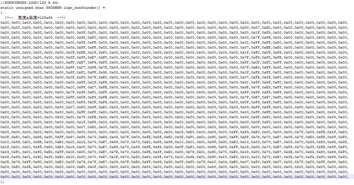
Figure 17
Third, program (please go to our official website www.sunfounder.com to download the example code by clicking LEARN -> Get Tutorials)
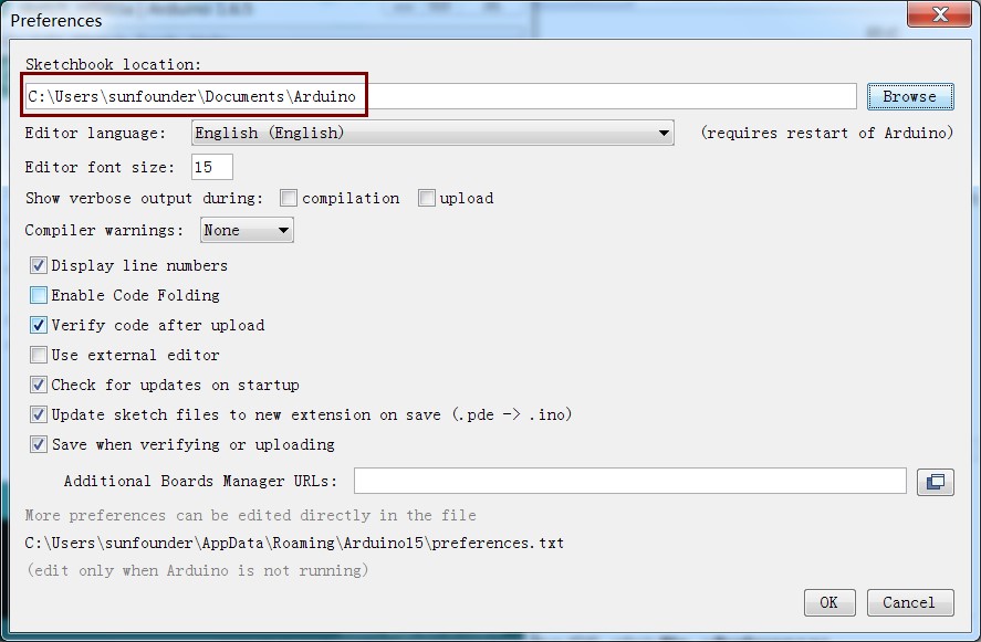
Fourth, since in some code, the libraries needed are not included in Arduino, so we need to add them before compiling. Add the files in the libraries folder under the path 11.OLED/code, i.e. the package you just downloaded, to the libraries folder in Arduino (if you cannot find the path in Arduino, open Arduino IDE, click File ->Preferences, and you can see the path on the top input box, as shown in the following diagram).
Fifth, burn the program into SunFounder Uno R3 board
After all the above steps, you will see the following phenomenon on OLED.
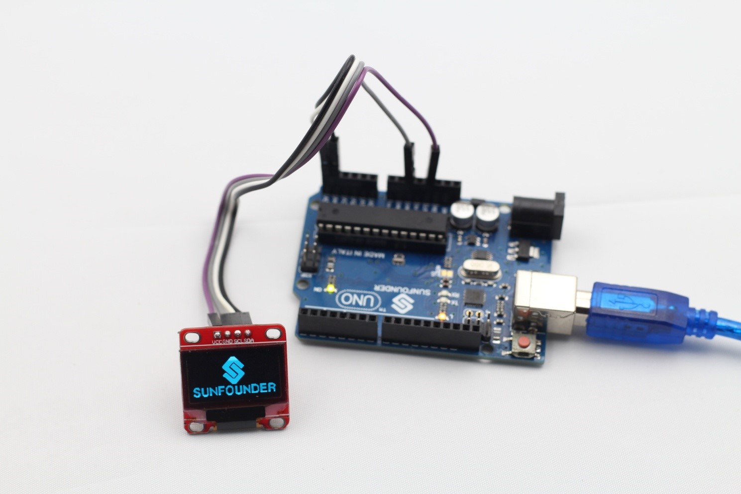
Figure 18
Experiment 2 Display Simple Graphics on OLED
Description: This routine will display some simple graphics and text on OLED.
Components:
SunFounder Uno R3 * 1
0.96 Inch OLED * 1
USB Cable * 1
Jumper Wires
Steps:
First, connect the circuit
SunFounder Uno OLED
SCL ——————————- SCL
SDA —————————— SDA
3.3V —————————— VCC
GND —————————— GND
Second, program (please go to our official website www.sunfounder.com to download the example code by clicking LEARN -> Get Tutorials)
Third, compile the program
Fourth, burn the program into SunFounder Uno R3 board
If everything goes well, you will see some basic patterns display on the OLED. The corresponding physical connection diagram is as shown in figure 19.
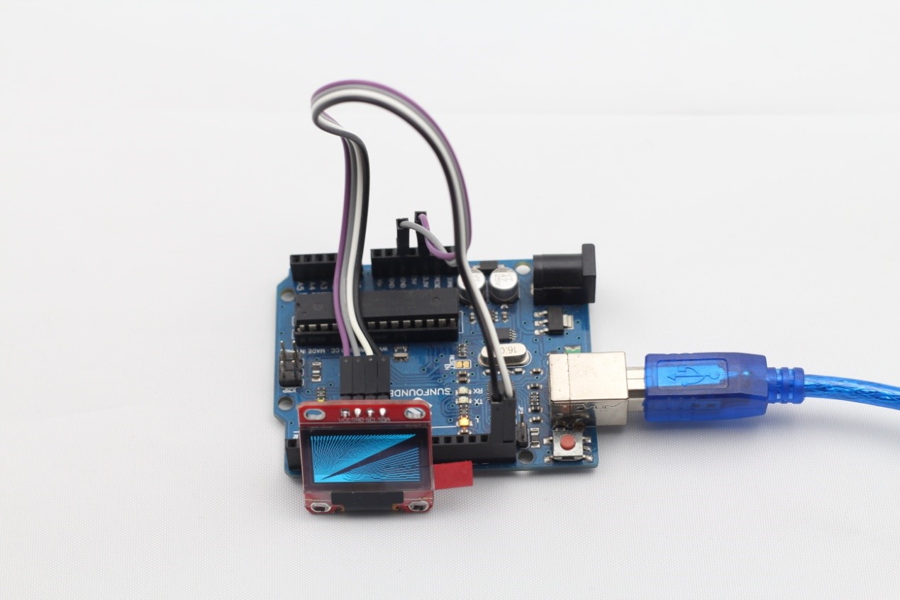
Figure 19
Experiment 3 Using OLED to display the Resistance of Photoresistor
Description: This routine will dynamically display the resistance of photoresistor on OLED with dynamic graphical effects.
Components:
SunFounder Uno R3 * 1
0.96 Inch OLED * 1
Photoresistor* 1
10K Ohm Resistor * 1
USB Data Cable * 1
Jumper Wires
Steps:
First, connect the circuit
SunFounder Uno OLED
SCL ————————————– SCL
SDA ————————————- SDA
3.3V————————————– VCC
GND ———————————— GND
The connection between SunFounder Uno and the photoresistor is as shown in figure 20:
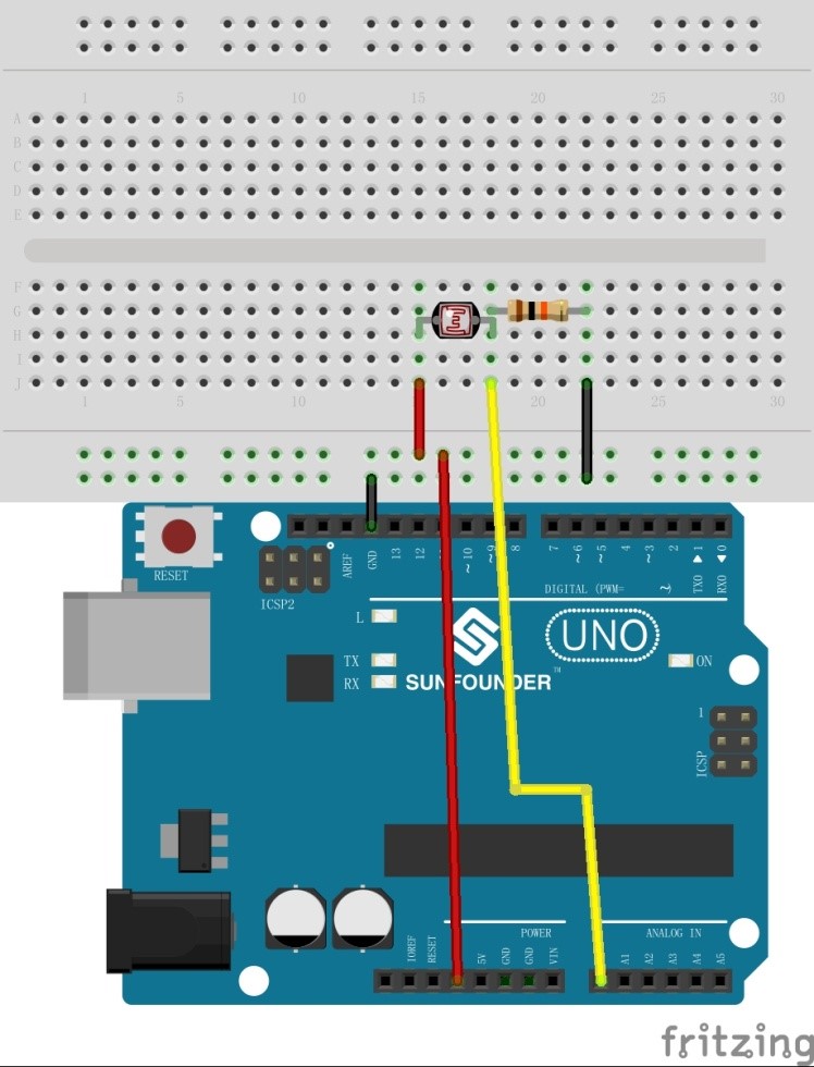
Figure 20
The corresponding principle diagram is as shown in figure 21:
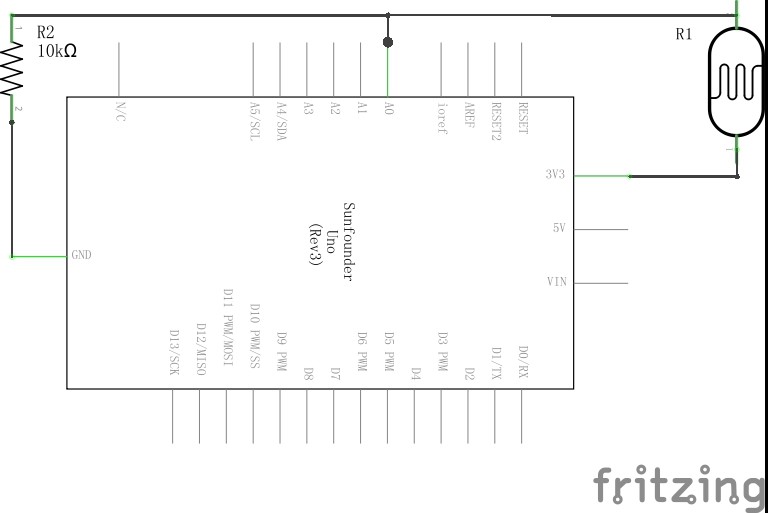
Figure 21
Second, program (please go to our official website www.sunfounder.com to download the example code by clicking LEARN -> Get Tutorials)
Third, compile the program
Fourth, burn the program into SunFounder Uno R3 board
You will see the height of bar that is used to indicate light intensity is proportional to light intensity, and the corresponding physical connection diagram is shown as figure 22:
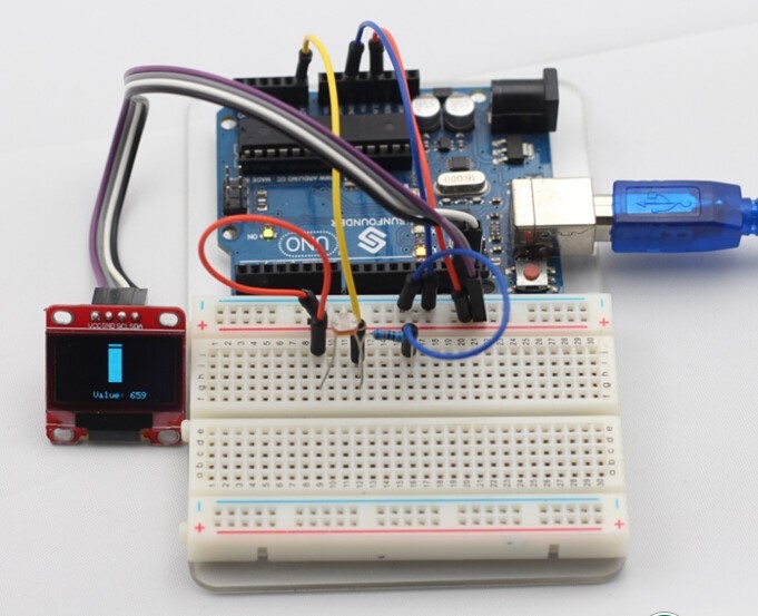
Figure 22
Experiment 4 Using OLED to Display the State of Tilt Switch
Description: In this routine, we will let OLED display the state of tilt switch. When the tilt switch remains level, the bulb displayed on the OLED will remain off; when the tilt switch tilts, the bulb will light up.
Components:
SunFounder Uno R3 * 1
0.96 Inch OLED * 1
Tilt Switch* 1
USB Cable * 1
Jumper Wires
Steps:
First, connect the circuit
SunFounder Uno OLED
SCL ————————————– SCL
SDA ————————————- SDA
3.3V ————————————- VCC
GND ———————————— GND
One end of the tilt switch is connected to GND on SunFounder Uno, and the other end is connected to digital port 5 on SunFounder Uno, as shown in figure 23:

Figure 23
Second, program (please go to our official website www.sunfounder.com to download the example code by clicking LEARN -> Get Tutorials)
Third, compile the program
Fourth, burn the program into SunFounder Uno R3 board
After all the above steps, when you lay the tilt switch horizontally, the bulb displayed on the OLED will remain off; when you tilt the tilt switch, the bulb will light up.
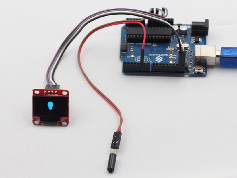
Figure 24
Experiment 5 Using OLED to Display Temperature and Humidity
Description: In this routine, we will let OLED dynamically display temperature and humidity values read from DHT11 with dynamic graphical effects.
Components:
SunFounder Uno R3 * 1
0.96 Inch OLED * 1
DHT11 * 1
USB Cable * 1
Jumper Wires
Steps:
First, connect the circuit
SunFounder Uno DHT11 OLED
D4 ——————————- S
5V ——————————- +
GND —————————— – ——————— GND
3.3V ——————————————————- VCC
SCL ——————————————————– SCL
SDA ——————————————————- SDA
Second, program (please go to our official website www.sunfounder.com to download the example code by clicking LEARN -> Get Tutorials)
Third, compile the program
Fourth, burn the program into SunFounder Uno R3 board
After all the above steps, you will see temperature and humidity data dynamically display on the OLED, the physical diagram is as shown in figure 25:
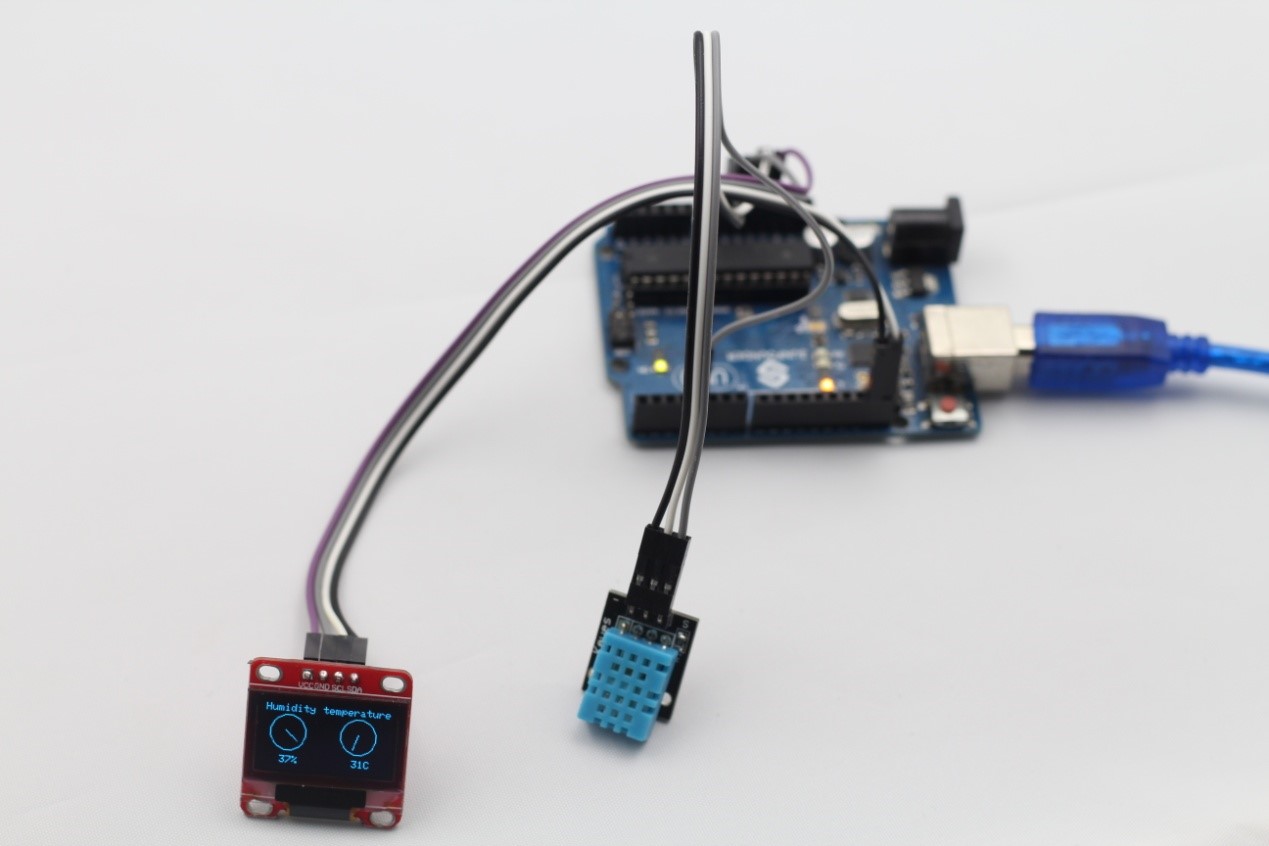
Figure 25
Experiment 6 Using OLED to Display 3-axis Acceleration Value
Description: In this routine, we will let OLED dynamically display acceleration values from 3-axis acceleration sensor ADXL345 with dynamic graphical effects.
Components:
SunFounder Uno R3 * 1
0.96 Inch OLED * 1
ADXL345 * 1
USB Cable * 1
Jumper Wires
Steps:
First, connect the circuit
SunFounder Uno ADXL345 OLED
5V ———————————– +
GND ——————————— “-“ ——————— GND
3.3V ———————————————————– VCC
SCL ————————————SCL——————– SCL
SDA ———————————- SDA ——————- SDA
Second, program (please go to our official website www.sunfounder.com to download the example code by clicking LEARN -> Get Tutorials)
Third, compile the program
Fourth, burn the program into SunFounder Uno R3 board
If everything goes well, you will see the OLED dynamically display the values of X, Y, Z axis measured by 3-axial acceleration sensor in real-time, the physical diagram is shown as figure 26:
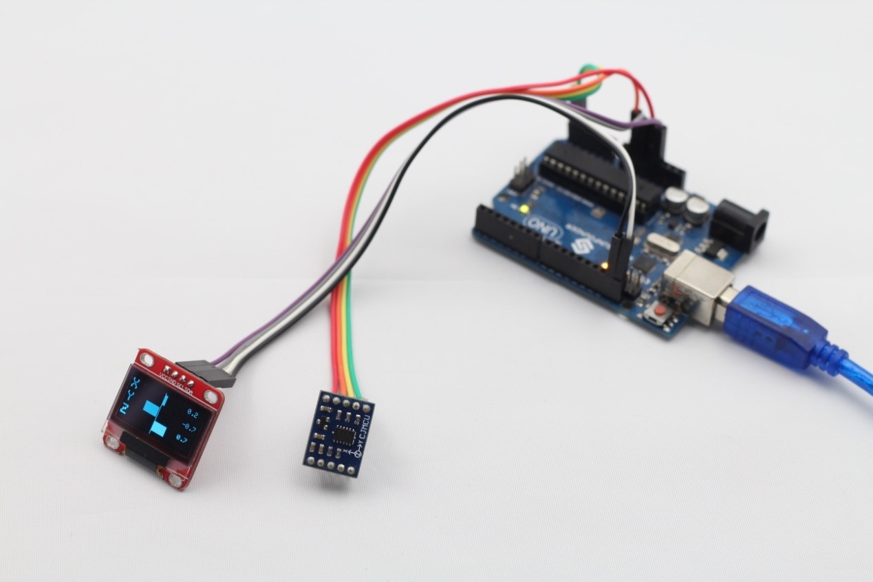
Figure 26
Experiment 7 Using OLED to Display PM2.5 Value
Description: In this routine, we will let the OLED display values read and operated from dust sensor GP2Y1010AU0F.
Components:
SunFounder Uno R3 * 1
0.96 Inch OLED * 1
GP2Y1010AU0F * 1
150 Ohm Resistor * 1
220 UF Capacitor * 1
USB Cable * 1
Jumper Wires
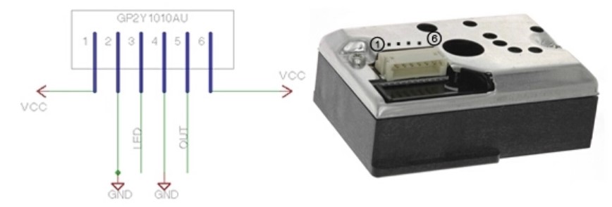
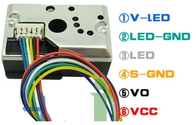
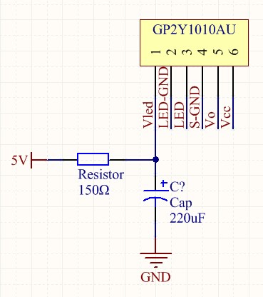
GP2Y1010AU0F Pins Description
Blue——–Vled
Green——-LED-GND
White——-LED
Yellow——-S-GND
Black——–Vo
Red———Vcc
Steps:
First, connect the circuit
SunFounder Uno GP2Y1010AU0F OLED
5V ——————————-Vled(150 Ohm resistor)
GND ——————————- LED-GND ———————– GND
D3 ————————————- LED
GND ——————————— S-GND
A1 ————————————– Vo
5V ————————————– Vcc
SCL ——————————————————————– SCL
SDA ——————————————————————- SDA
3.3V ——————————————————————- VCC
Connect a 150 Ohm resistor to pin Vled of GP2Y1010AU0F and then connect it to pin 5v of SunFounder Uno, meanwhile, connect the other end of pin Vled to the positive pole of 220UF capacitor and connect the negative pole of the capacitor to GND.
Second, program (please go to our official website www.sunfounder.com to download the example code by clicking LEARN -> Get Tutorials)
Third, compile the program
Fourth, burn the program into SunFounder Uno R3 board
If everything goes well, you will see PM2.5 values displaying on the OLED. The physical diagram is shown as figure 27:
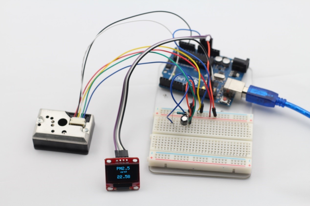
Figure 27
Experiment 8 Using OLED to Display Air Pressure and Elevation
Description: In this routine, we will let OLED display air pressure and elevation values read and operated from air pressure sensor BMP180.
Components:
SunFounder Uno R3 * 1
0.96 Inch OLED * 1
BMP180 * 1
USB Cable * 1
Jumper Wires
Steps:
First, connect the circuit
SunFounder Uno BMP180 OLED
SDA ——————————– SDA ——————- SDA
SCL ——————————— SCL ——————– SCL
5V ———————————- VIN
GND ——————————– GND —————— GND
3.3V ———————————————————- VCC
Second, program (please go to our official website www.sunfounder.com to download the example code by clicking LEARN -> Get Tutorials)
Third, compile the program
Fourth, burn the program into SunFounder Uno R3 board
After all the above steps, air pressure, elevation, temperature information collected by BMP180 will display on the OLED. It will reflect the weather forecast through pictures. The physical diagram is as shown in figure 28:
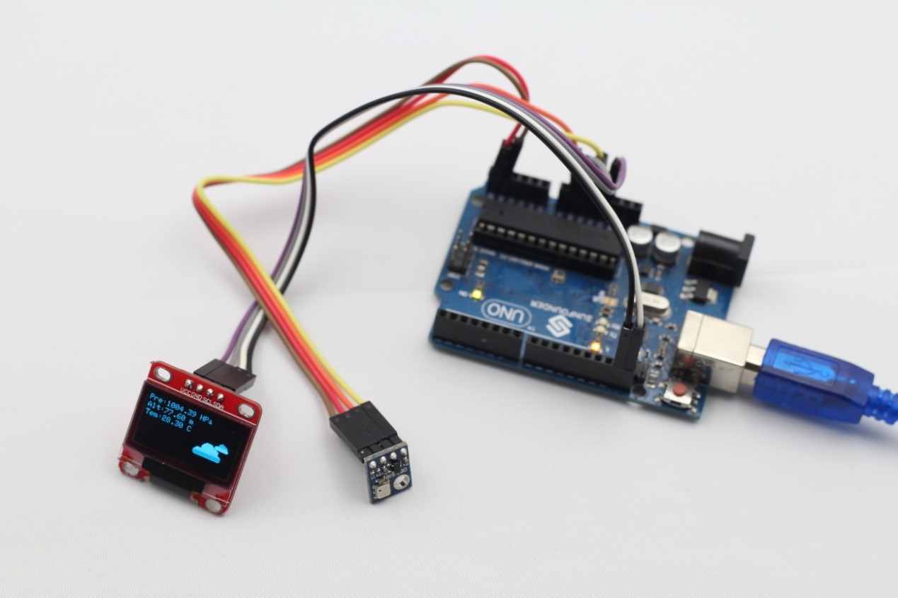
Figure 28
Experiment 9 Joint Application
Description: In this routine, we will use all the above sensors with OLED to joint test. The OLED uses menu to manage, so you can easily see the sensor values you have selected by menu options. And rotary encoder comes in handy here. By rotating the handle of rotary encoder, you can choose the sensor you want. By pressing the switch, you can enter into the selected sensor interface.
Components:
SunFounder Uno R3 * 1
0.96 Inch OLED * 1
Photoresistor * 1
10K Ohm Resistor * 1
Tilt Switch* 1
DHT11 * 1
ADXL345 * 1
GP2Y1010AU0F * 1
150 Ohm Resistor * 1
220 UF Capacitor * 1
BMP180 * 1
USB Cable * 1
Jumper Wires
Steps:
First, connect the circuit
SunFounder Uno BMP180
D4 ———————————– S
5V ———————————– +
GND ——————————— –
SunFounder Uno DHT11
D4 ———————————- S
5V ———————————- +
GND ——————————- –
SunFounder Uno ADXL345
SCL ——————————— SCL
SDA ——————————– SDA
5V ———————————– +
GND ——————————— –
SunFounder Uno GP2Y1010AU0F
5V ——————————-Vled(150 Ohm resistor)
GND ——————————- LED-GND
D3 ————————————- LED
GND ——————————— S-GND
A1 ————————————– Vo
5V ————————————– Vcc
SunFounder Uno BMP180
SDA ——————————– SDA
SCL ——————————— SCL
5V ———————————- VIN
GND ——————————– GND
SunFounder Uno OLED
SCL ——————————— SCL
SDA ——————————– SDA
3.3V——————————— VCC
GND ——————————– GND
SunFounder Uno ENCODER
5V ———————————— +
GND ——————————— GND
8 ————————————- CLK
9 ————————————- DT
10 ———————————— SW
(Connect a 104 ceramic capacitor between pin CLK of ENCODER and GND and pin DT of ENCODER and GND, and the connection between SunFounder Uno and photoresistor and the connection between SunFounder Uno and the tilt switch is shown as figure 29)
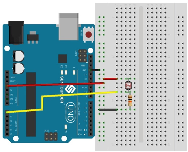
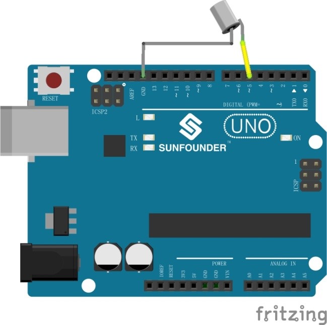
Figure 29
Second, program (please go to our official website www.sunfounder.com to download the example code by clicking LEARN -> Get Tutorials)
Third, compile the program
Fourth, burn the program into SunFounder Uno R3 board
After you have finished all the above steps, rotate the rotary encoder to select the sensor you want to know and press the switch on the rotary encoder, then you can enter into the corresponding sensor interface to see related information. The physical diagram is as shown in figure 30: