With a good foundation of Arduino, you can use SunFounder Leonardo easily. If you are totally new to Arduino, visit https://www.arduino.cc/.
It will still be good if you’ve only learnt C/C++ language. Visit https://www.arduino.cc/en/Main/Software to download and install Arduino software and get started.
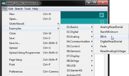
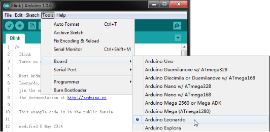
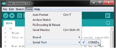
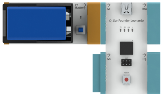
Connect C3 SunFounder Leonardo to your PC with a USB cable. Open Arduino IDE, click File>Examples>01.Basics>Blink, then Tools>Board>Arduino Leonard, and last Tools>Serial Port>COM25 (depending on real situations). Then click Upload.
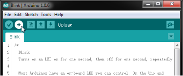
Now, the white LED on C3 SunFounder Leonardo starts to blink.
Or, you can remove the USB cable. Connect the P1 Battery block to the left of C3. Switch on P1 Battery. C3 SunFounder Leonardo also works.
The comments of the example describes how it happens in detail.
// the setup function runs once when you press reset or power the board
void setup()
{
  // initialize digital pin 13 as an output.
  pinMode(13, OUTPUT);
}

// the loop function runs over and over again forever
void loop()
{
  digitalWrite(13, HIGH);	// turn the LED on (HIGH is the voltage level)
  delay(1000);			// wait for a second
  digitalWrite(13, LOW);	// turn the LED off by making the voltage LOW
  delay(1000);			// wait for a second
}
C3_Demo
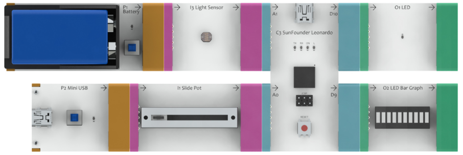
Try the following connection. Connect C3 to your PC with a USB cable. Go to EC-Block Analog Kit\C3_Code\C3_Demo\C3_Demo.ino with Arduino IDE, open the file and upload the sketch. Try to drag the slider of I1, or cover I3 with your palm and observe what happens.
Note:
When you connect Input blocks to the left of C3, a Power block should be connected to the Input block. Otherwise, the Input block will output 0 all the time. You may or may not switch on the Power block.
Let’s take a look at how this is done by code. In each example code, several functions are provided.
void C3Setup(void)          // C3 port setup, must be called in setup().

byte readA0(void)           // Read analog value of A0 port.

byte readA1(void)           // Read analog value of A1 port.

void writeD9(byte value)    // Write analog value to D9 port.

void writeD10(byte value)   // Write analog value to D10 port.
These functions are easy to use. The value, no matter it is read from or written to a port, is between 0 and 100.
Before the reading or writing of a port, void C3Setup() must be called in setup().
void setup()

{

  C3Setup();                 // Setup the port of C3

}
In the loop() function, read the value from A0 and then write it to D9, and read the value from A1 and then write it to D10.
void loop()
{
  /* Put your code here ---------------------------------------------------- */

  byte value;				// Define a variable to record value

  // Code below show how to read analog value of A0 and write it to D9.
  value=readA0();			// Read analog value of A0 port
  writeD9(value);			// Write analog value to D9 port

  // Code below show how to read analog value of A1 and write it to D10.
  value=readA1();			// Read analog value of A1 port
  writeD10(value);			// Write analog value to 10 port

  /* End of your code ------------------------------------------------------ */
}
You can modify the code. For example, read the value from A0 and write it to D10. Read the value from A1 and write it to D9.
What you need to do is exchange the two lines.
  value=readA0();			// Read analog value of A0 port
  value=readA1();			// Read analog value of A1 port
For detailed code, refer to C3_Exchange.ino.
C3_Inverter
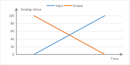
Now, to learn further, use C1 Inverter to stimulate C3. Inverter is used to invert signals. That is, subtract the input signal from 100, and then output the result.
Start building. Connect C3 to your PC with a USB cable. Go to EC-Block Analog Kit\C3_Code\C3_Inverter\C3_Inverter.ino, open the file with Arduino IDE and upload the sketch.
Now, C3 can function as C1 does. Let’s check the code.
void loop()
{
  /* Put your code here ---------------------------------------------------- */

  byte value;				// Define a variable to record value
  value=readA1();			// Read analog value of A1 port
  value=100-value;			// Invert the value
  writeD10(value);			// Write analog value to D10 port

  /* End of your code ------------------------------------------------------ */
}
You can try to modify the code. Change C3 to a two-channel C1. This may not a problem for you after learning. For more details, refer to C3_Inverter_2Way.ino.
C3_Trigger
Trigger is widely used in circuit design. Set a reference value first. When the input analog value is greater than the reference value, it will output the maximum value; when the input value is smaller than the reference value, it will output the minimum value.
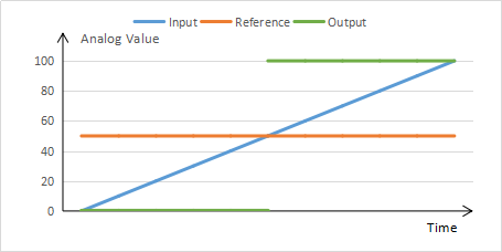
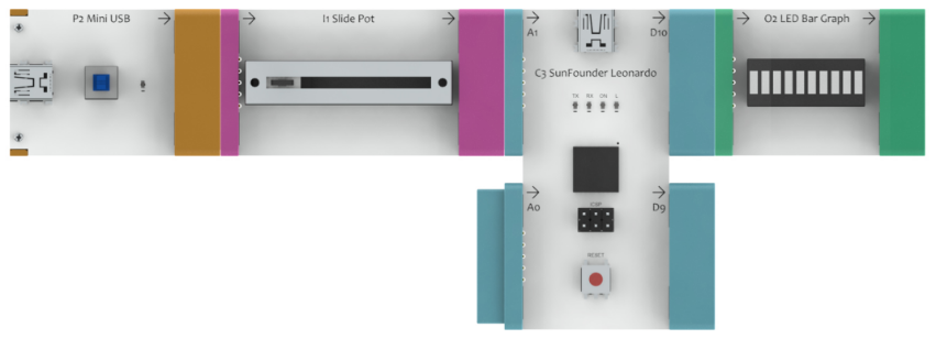
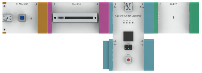
Now we use C3 to realize this function. Connect the blocks as shown below, open EC-Block Analog Kit\C3_Code\C3_Trigger\C3_Trigger.ino and upload the code. Drag or pull the slider. If the slider is at left-center, the LED on O1 will not light up. If it is at right-center, the LED on O1 will light up.
In the code, we set a reference value 50 first.
byte reference_value=50;In loop() function, compare the analog values read with the reference value, and then output the signal according to the comparison result.
void loop()
{
  /* Put your code here ---------------------------------------------------- */

  byte value;				// Define a variable to record value
  value=readA1();			// Read analog value of A1 port
  if(value>reference_value)
    writeD10(100);			// Bigger than reference value, Write 100 to D10 port
  else
    writeD10(0);			// Less than or equal to reference value, Write 0 to D10 port

  /* End of your code ------------------------------------------------------ */
}
C3_Oscillator
Now, you may try something more complicated. Use C3 to simulate C2 Oscillator. C2 generates oscillation waves and the oscillation period can be adjusted by the Input block connected on the left.
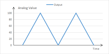
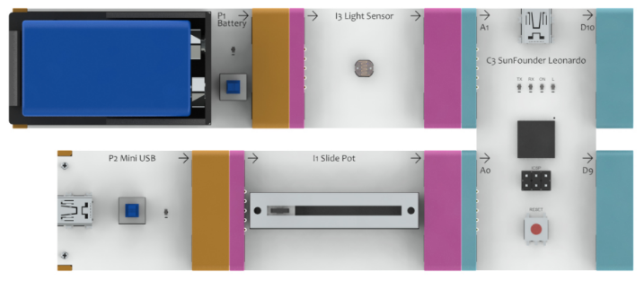
Use the following connection to verify the code. If it is correct, the LED on O1 will get brighter gradually and then turn into dimmer, forming a cycle. I1 can change the speed of O1 changing its brightness.

You may need to solve two problems here: generating oscillation waves and controlling the oscillation period.
Go to EC-Block Analog Kit\C3_Code\C3_Oscillator\C3_Oscillator.ino and open the file to check the code.
The loop() function is executed circularly. Thus, the output is changed each time the function is run. Eventually our aim can be achieved by the constantly changing the output.
You need to output a value from 0 to 99, 100 to 1 and then repeat this cycle. So first, you need to define a variable.
static byte counter; // Define a variable to count cycle timesModify the variable with static – as declared static, the variable will not be initialized again to 0. First make this variable cycle from 0 to 199.
counter<199?counter++:counter=0;Then you’ll get a value cycling from 0 to 99, 100 to 1 continuously. Write it into a defined variable valueWrite and output it.
  counter<100?valueWrite=counter:valueWrite=200-counter;
  writeD10(valueWrite);
Now, oscillation waves have been generated. Next, control the oscillation period. You can realize the control by the period of the loop() function. Here you need to use the delay() function.
  valueRead=readA1();		// Read analog value of A1 port
  valueRead=100-valueRead;	// Invert the value
  valueRead=valueRead*0.2;	// Make it smaller
  valueRead=valueRead+2;	// Avoid frequency too fast
  delay(valueRead);		// Delay some time according to analog value of A0
To sum it up, read the value from A1, invert the value, and delay a period of time so as to control the oscillation period.
C3_Serial_Send
Now, try to use C3 to communicate via the serial port – send the values read from A1 and A0 to your computer. Connect the follo
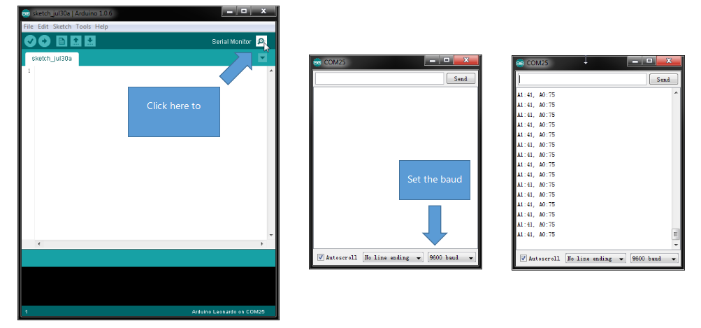
You can use the serial port to communicate easily. The C3 board has integrated the serial port function. Connect it with your computer and open Serial Monitor. Go to EC-Block Analog Kit\C3_Code\C3_Serial_Send\C3_Serial_Send.ino, open the file and upload the sketch. Keep the USB connection.
The two devices, which communicate with each other by serial port, must share the same baud rate, that is, transmission rate. In the sketch just uploaded to C3, the rate we use is 9600 baud. After upload, open Serial Monitor and set the rate as 9600 baud, and then you can see the data transferred from C3.
In the setup() function, you need to open the serial port and set the baud rate. Then wait for the serial port to get ready.
void setup()
{
  C3Setup();			// Setup the port of C3
  Serial.begin(9600);		// Start serial port at 9600 bps
  while (!Serial);		// Wait for serial port to connect. Needed for Leonardo only
}
Then read values from A1 and A0 and send them in the loop() function.
  byte value;			// Define a variable to record value

  value=readA1();		// Read analog value of A1 port
  Serial.print("A1:");		// Print "A1:" to serial
  Serial.print(value);		// Print A1 value to serial
  value=readA0();		// Read analog value of A0 port
  Serial.print(", A0:");	// Print ", A0:" to serial
  Serial.println(value);	// Print A0 value to serial

  delay(100);
C3_Serial_Receive
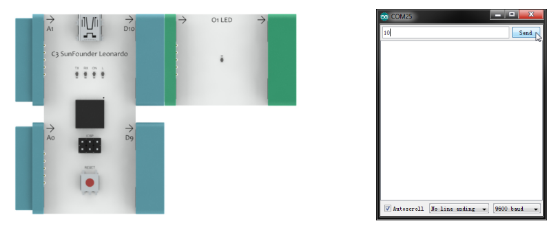
You have tried to send data via the serial port. Now use the serial port to receive data. Connect the following blocks, go to EC-Block Analog Kit\C3_Code\C3_Serial_Receive\C3_Serial_Receive.ino, open the file and upload the sketch. Keep the USB connection.
Open Serial Monitor, and set the rate as 9600 baud. Type in a number between 0-100 in the box. Click Send. C3 will output the analog value to D10.
In the setup() function, you need to open the serial port and set the baud rate, and then wait for a while. Also you need to set the timeout of the serial port. As the serial port transfers data one byte each time, if several bytes are sent continuously, they will be deemed as a piece of data. If the interval between two bytes is overlong, they will be taken as separate data. The timeout of the serial port is the basis to distinguish between normal and overlong interval time.
void setup()
{
  C3Setup();			// Setup the port of C3
  Serial.begin(9600);		// Start serial port at 9600 bps
  Serial.setTimeout(100);	// Set maximum milliseconds to wait for serial data
  while (!Serial);		// Wait for serial port to connect. Needed for Leonardo only
}
Then in the loop() function, check whether data is received. If yes, read it and judge whether it is within the range. If yes, output the data.
int value;				// Define a variable to record value

if(Serial.available() > 0)		// If there's serial available
{
  value = Serial.parseInt();		// Read value from serial
  if(value<0||value>100)		// If out of range, send a message
    Serial.println("Out of range!");
  else
  {					// If in the range
    writeD10(value);			// Write it to D10 port
    Serial.println(value); 		// Print it to serial
  }
}